<< This is a continuation of Workbench: Part 6 – Finishing the benchtop
The finish has been applied to the bench-top so now it’s time to attach the hardware. This is a tricky subject to explain clearly. I’m going to do my best but I’m planning on coming back and editing this post a bit in an effort to clear some things up. That being said, if any of my explanations below are confusing, please leave me a comment and I’ll try explaining it in more detail.
This post has a lot of pictures so be patient while it loads.
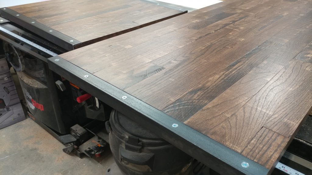
Attaching the angle iron to the ends of each piece.
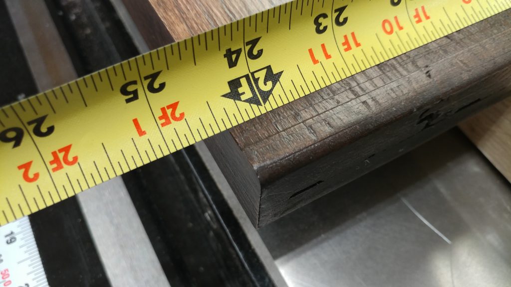
The bench-top is 23-7/16″ deep so I need to cut four pieces of angle iron to that length.
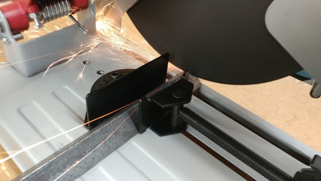
A metal chop saw was used to make all my cuts but you can do this with a hacksaw if you don’t mind the blisters and carpal tunnel.
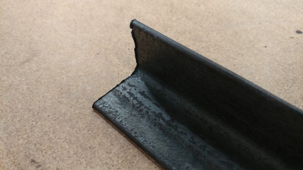
The chop saw leaves a jagged burr on the edge of the angle iron so I’ll need to knock that back.
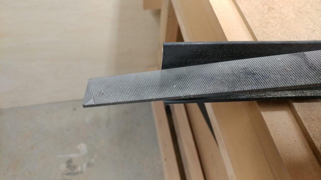
You can use a hand file to remove most of the burr from each end of the pieces of angle iron. I did this while slightly rounding over the ends.
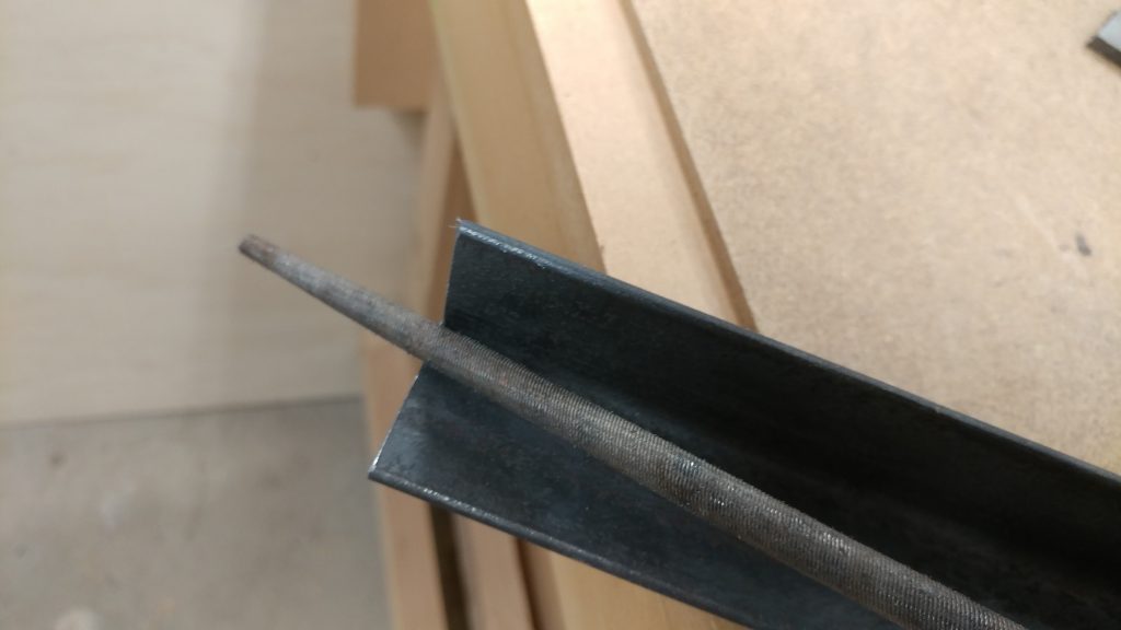
To remove the burr on the inner corner I needed to use a rat-tail file.
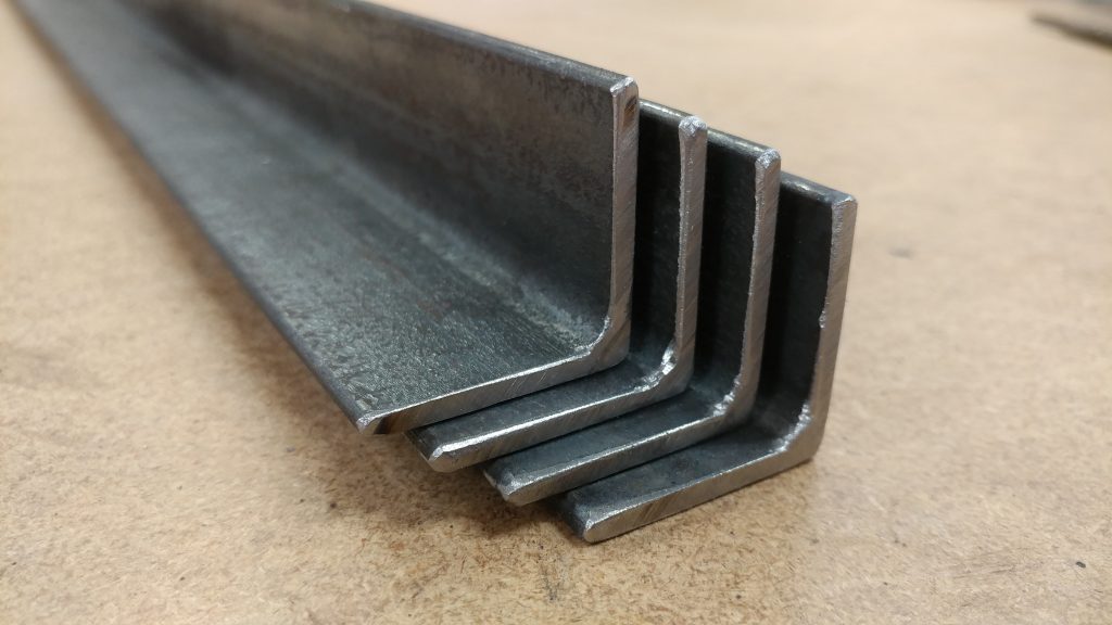
The burrs were removed from both ends of each piece of angle iron.
A test fit gives a preview of how it looks and lets you make sure that none of the metal pieces are too long.
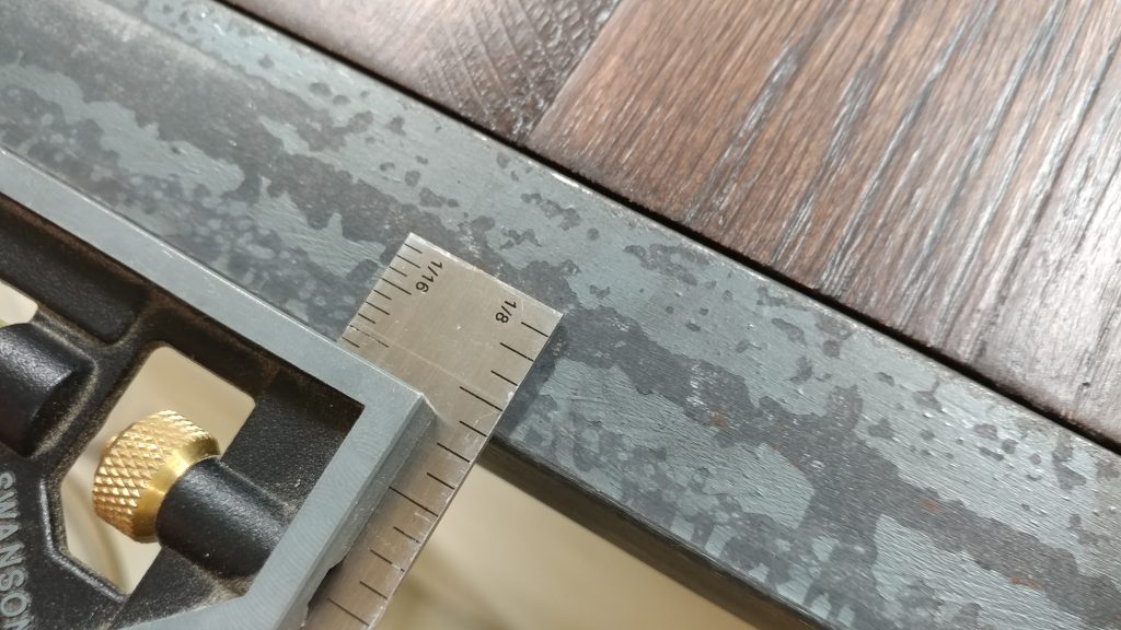
The screws will be attached in the center of the angle iron so I set my combination square to half the width which ended up being 5/8″.
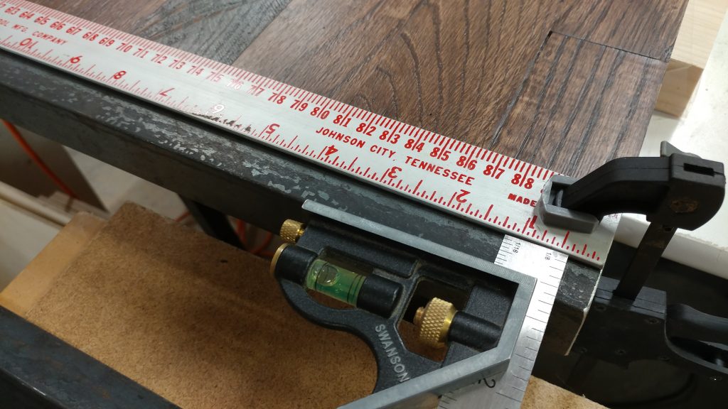
I used the combination square to set the position of a metal shop rule on the angle iron and I clamped it in place.
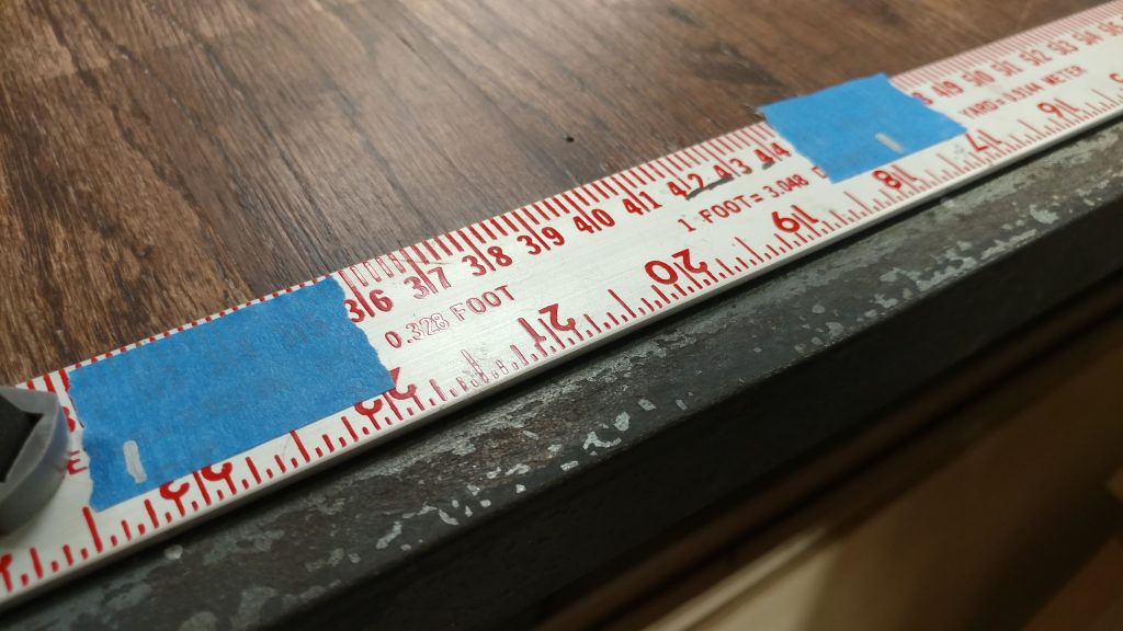
I decided on the placement of the screws by first marking where the center screw will be and then adding the marks for the outer screws about 1-1/4″ inches in from the edge. I then found the center point between the outer marks and the central one. I used a silver Sharpie to mark the placement of the screws with some hash marks on pieces of painters tape so I could repeat them on each piece.
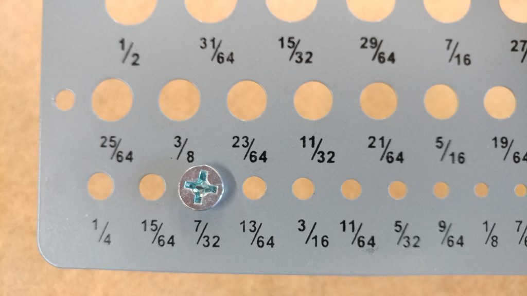
The screws that I am using to attach the metal require a 7/32″ hole.
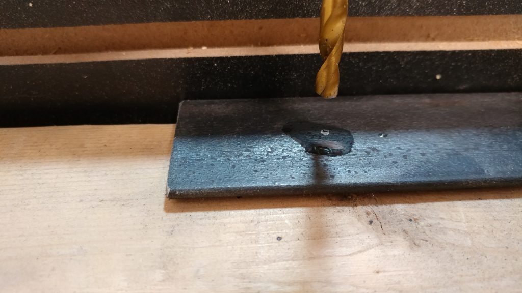
When drilling through metal you should usually apply a few drops of 3-in-1 oil to where you will be drilling out the holes. This is what I did when I made the holes using a drill press.
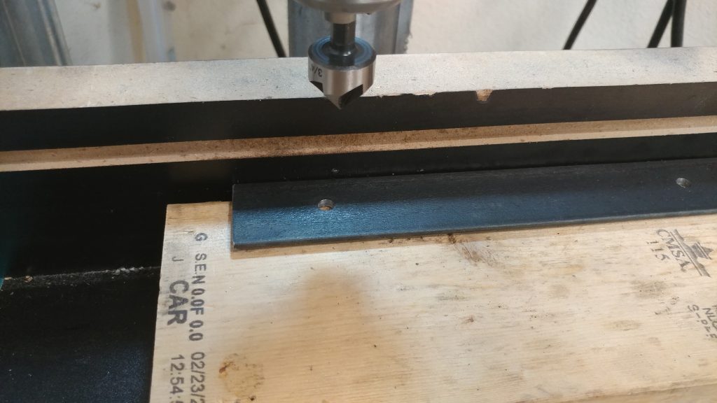
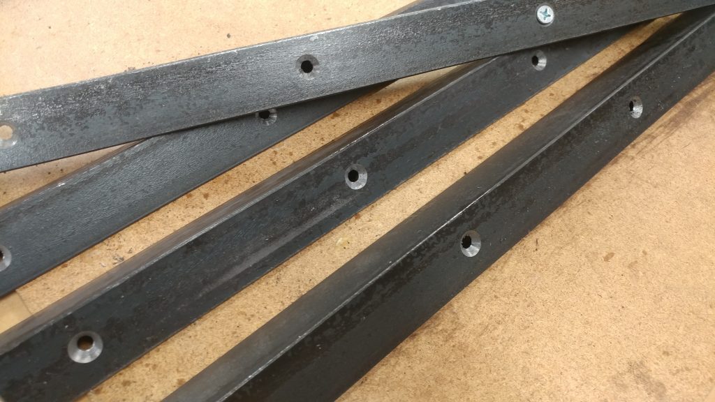
Since I wanted the screws to sit relatively flush with the top of the metal, I added a countersink to each hole using a 3/4″ countersink bit. I went just deep enough for them to be flush but I didn’t want it too perfect since I’m going for a more used, industrial look. Fortunately, making things “not perfect” is a specialty of mine.
This took quite a while. I ended up doing most of them with a hand drill which actually went much faster than the drill press and helped contribute to the imperfect look that I was going for.
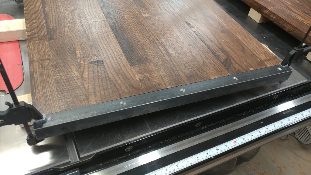
When it was time to drill the holes, I clamped the angle iron to the ends of the bench-top pieces so I could ensure their placement was correct and that it wouldn’t slip.
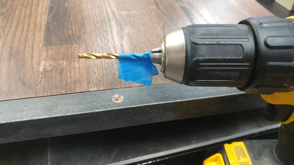
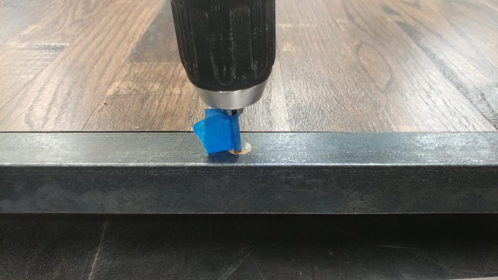
I used some blue painters tape on my drill bit to mark the depth of the hole that I needed for the screws.
I drilled just to the point that the painters tape touched the metal. This is easy to do if you watch the shavings that gather around the hole you are drilling. When the tape starts to brush them aside, stop drilling.
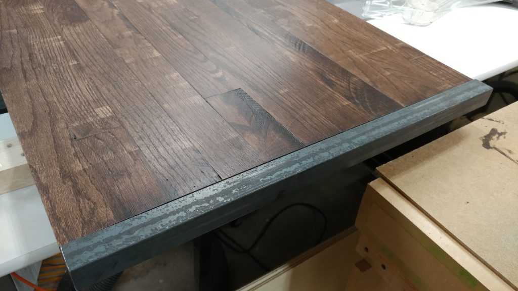
The pieces were then attached with screws. Now the bench-tops are officially done.
Attaching the legs to the bench-top.
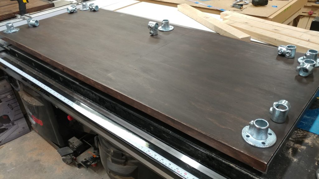
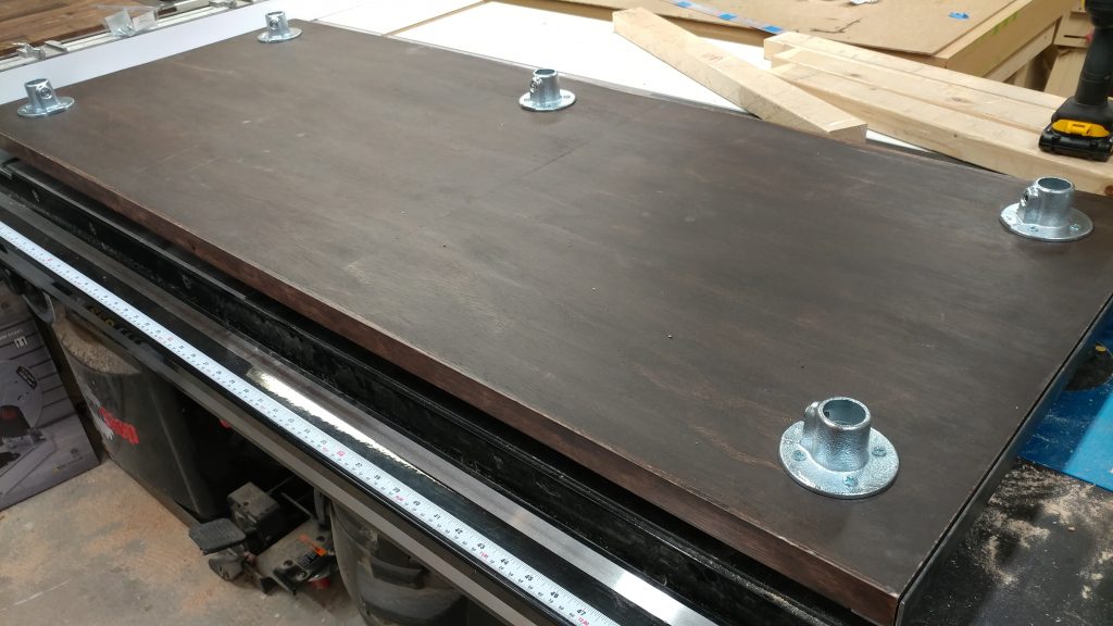
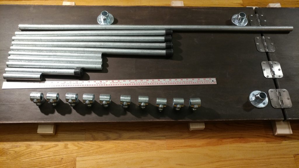
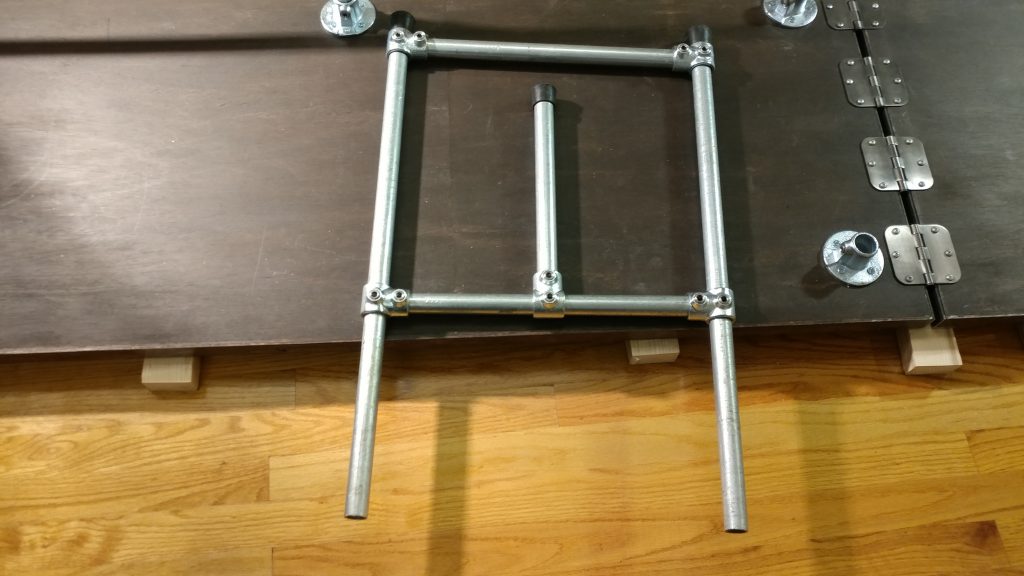
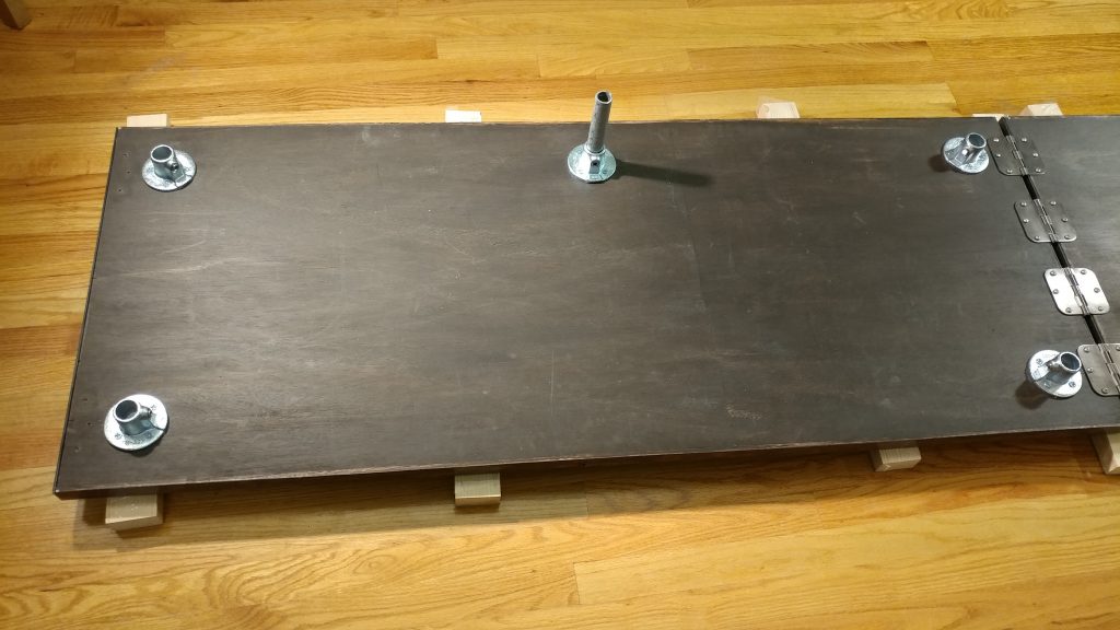
I am using hardware by Steel-Tek to create the legs for this desk. To get a visual on what pieces are needed where, I laid them out on the underside of the bench-top in the approximate area where they will be attached.
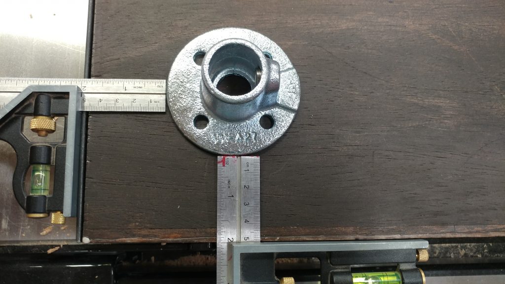
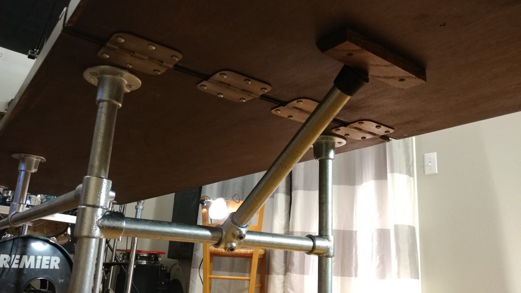
I attached a 3/4″ flange (part no. 673-104HC) in each of the four corners of the main bench-top piece. I set them 2″ in from each edge.
Four screws were used to attach each flange. I also added a fifth flange along the back edge which will help support the bench-top along the length.
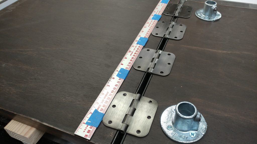
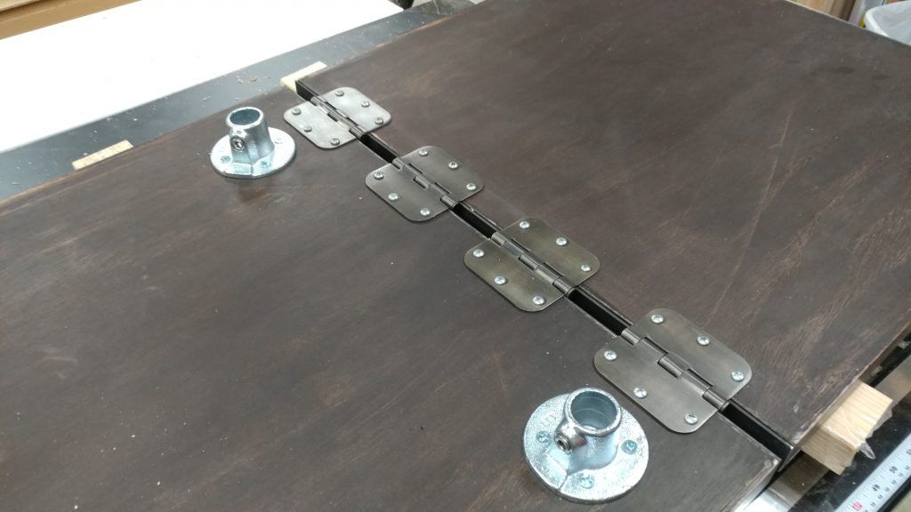
Since I still had the hash marks on my shop rule from when I drilled the holes in the angle iron, I laid that out and used it to arrange the hinges for attaching the extension wing. I debated about using a piano hinge for this as it would provide better support since it would be screwed into the side rather than from underneath. In the end, I decided to attach four hinges along the underside and I’ll just keep an eye on it. I can always come back and change it later if it starts to weaken.
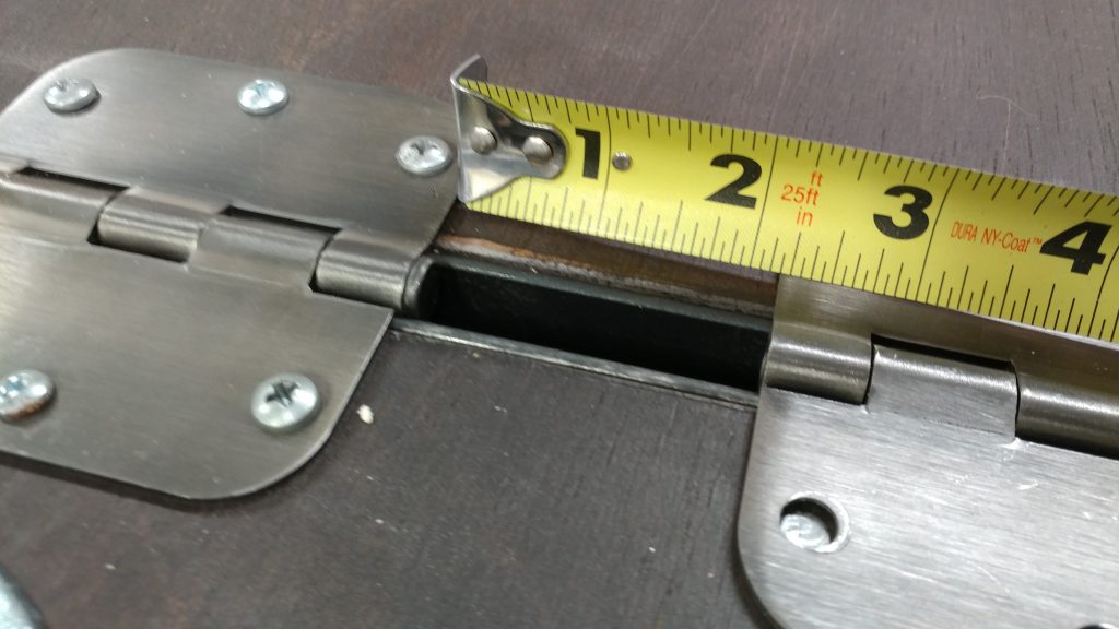
I ended up spacing the hinges a little over 2″ apart. This measurement will vary depending on the hinge that is used.
Each hinge was attached and they seem really solid so I’m not too worried. I needed a slight gap between the main table and the wing because of how the wing is going to be held upright. This will be explained later.
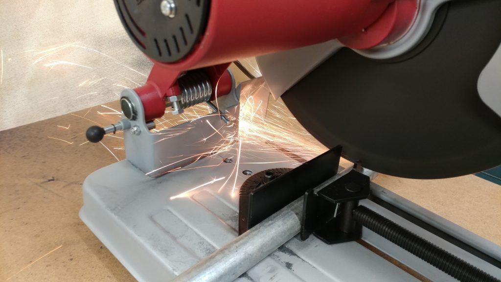
Back to my chop saw to cut down the 3/4″ tubing to the various lengths that I needed.
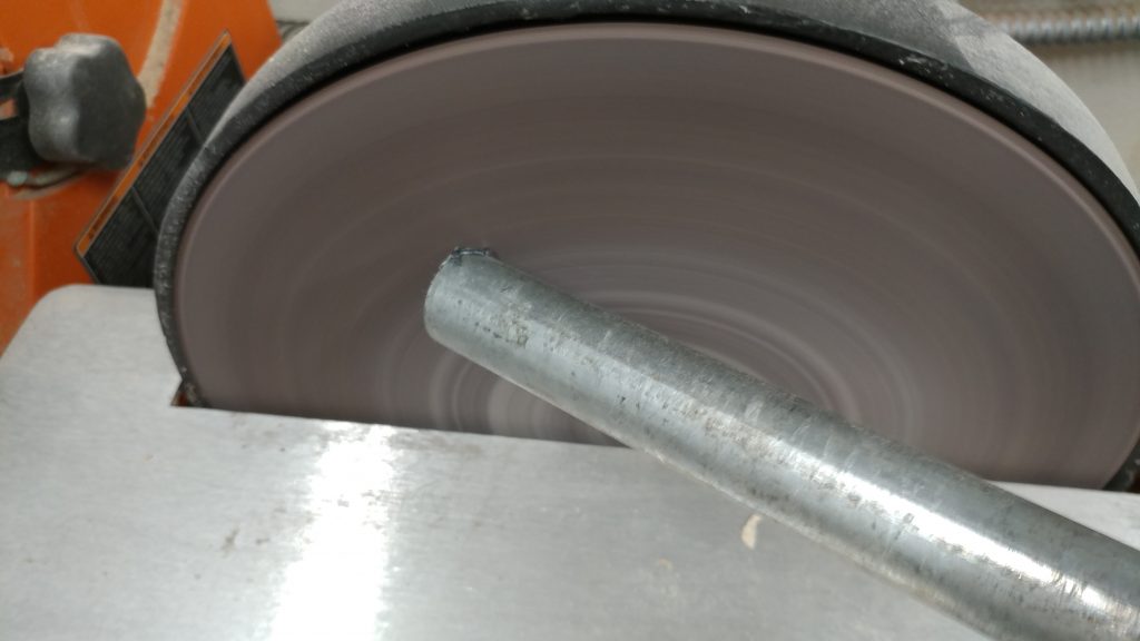
Using a disc sander, I added a slight chamfer around the edge of each piece of pipe in case anyone wants to take this bench apart in the future. I wouldn’t want anyone getting cut on the sharp edges.
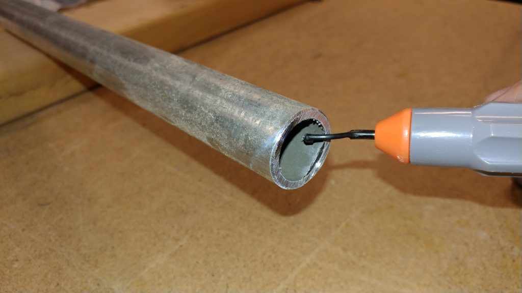
As I was cutting these down, I realized that this piping would allow me to run wires through them in case I wanted to add a few outlets along the top. If you’ve ever run conduit, you probably understand the importance of removing the jagged edge along the inside so it doesn’t damage any wires. I did this with a deburring tool.
I got all my hardware gathered up. Along with ten single socket tees (670-104HC) from Steel-Tek, I used the following lengths of pipe.
- (qty: 1) 52″
- (qty: 4) 28 ¼”
- (qty: 3) 16″
- (qty: 1) 12 ½”
- (qty: 1) 6″
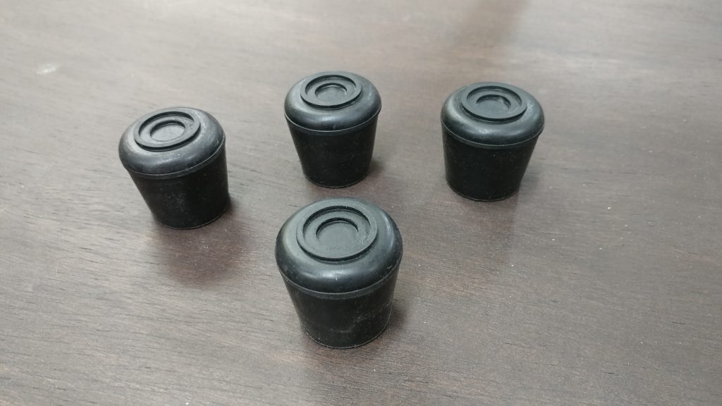
I also used 1″ rubber feet which fit perfectly over the 3/4″ pipe. Four of these were used for the legs and a fifth was used for the extension wing support arm.
I inserted the 6″ piece of pipe into the center flange and tightened the set screw.
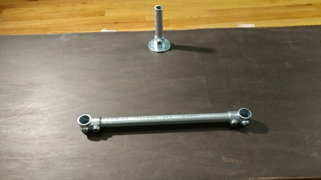
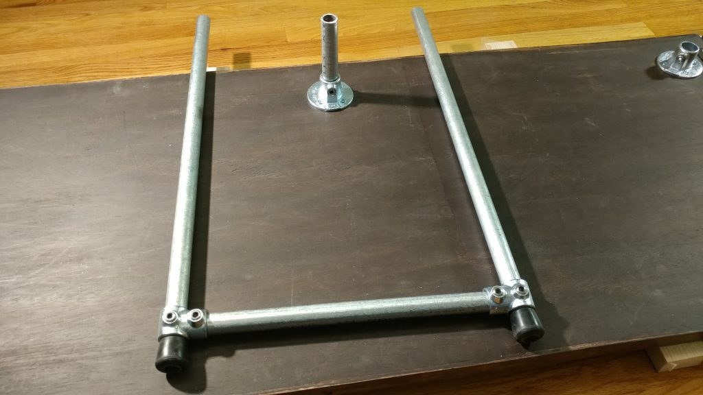
Two single socket tees are then attached to two of the three 16″ lengths of pipe and the set screws are tightened. These will be the horizontal support braces that will go between the front and rear legs.
I slid two legs all the way through the tees on each of the horizontal braces and temporarily tightened the set screws. I set these aside for later.
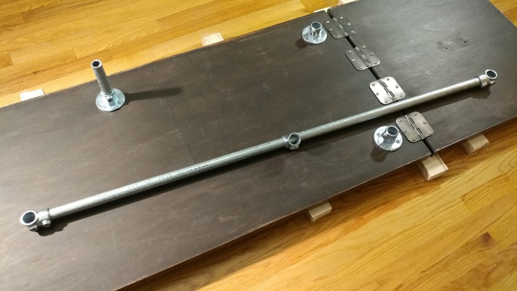
Then I attached three of the tees to the 52″ length of pipe. First I attached one on the end and tightened down the set screw. After that I slid one of the tees over the pipe and moved it towards the center but didn’t tighten it at all. I then added the last tee to this piece and tightened it up.
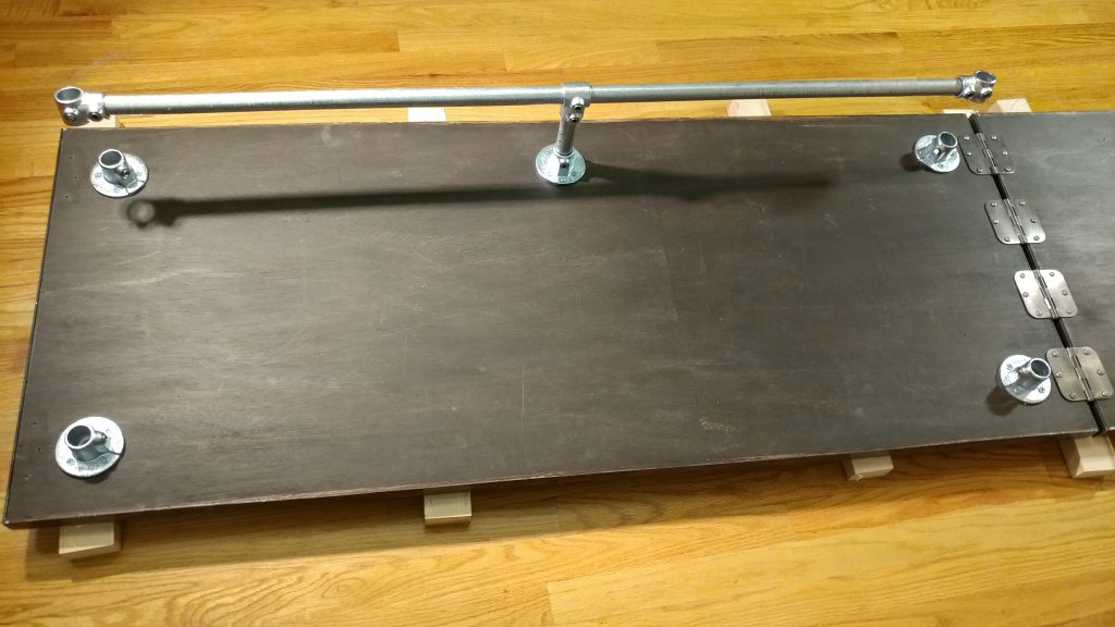
Once it was all together I fit the loose central tee over the other end of the 6″ pipe and tightened the set screw but only the one that attaches it to the shorter piece. This meant the large 52″ piece can slide around if I need it to while I’m attaching the legs.
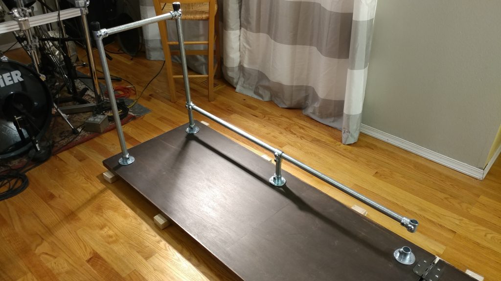
At this point, the only piece of pipe that is secure is the 6″ piece. This let me insert one of the sets of legs into the flanges on the side without the extension wing. I made sure the legs were square with the bench-top and tightened down the set screws in the flanges. The tee that attaches the rear rail to these legs is still loose. It’s worth noting that I have all of the set screws one every fixture facing the inside of the desk. This will make it easier to remove the bench-top from the legs without having to move the bench away from the wall.
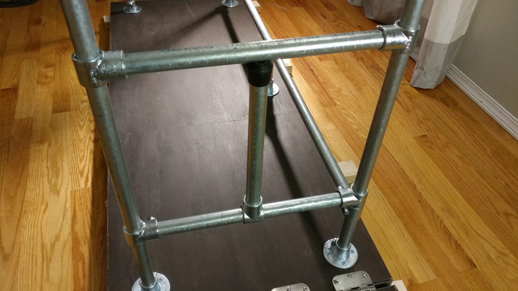
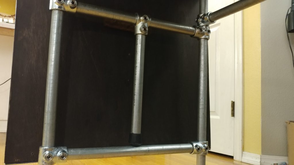
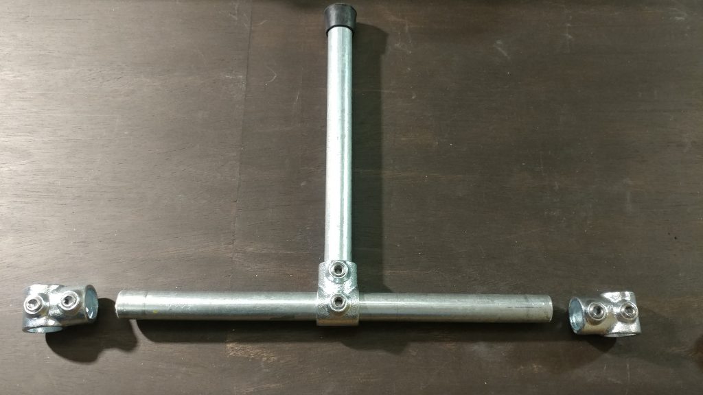
The extension wing support is next. I put this together somewhat similarly to the rear rail except I centered the tee and tightened it down. I also inserted the 12-1/2″ piece with the rubber foot on the opposite end. I tightened this set screw but knew I would probably have to come back and adjust this later. The two tees on the end are kept loose and will remain so.
The extension table support is then slid on to the other set of legs. To make attaching it easier, I temporarily tightened the set screws for the tees that attach it to the legs.
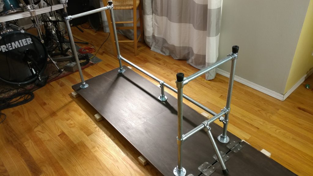
This leg assembly is inserted like the opposite one. Make sure it is square to the bench-top and tighten the set screws on the flanges. Then, I ensured that the rear rail was the same distance from the underside of the bench-top at either end and tightened the set screws on the tees at each end of the rear rail.
Then I loosened the set screws on the tees that attach the extension wing arm support to the legs and slid them down so the rear tee rested on top of the tee on the rear rail. I tightened it down and set the opposite tee on this piece to the same height and secured it as well. I then lowered the horizontal brace so it rested on the rubber foot of the extension wing arm and tightened it down. Once that was in the correct position, I took a measurement and duplicated this position on the horizontal brace on the other legs.
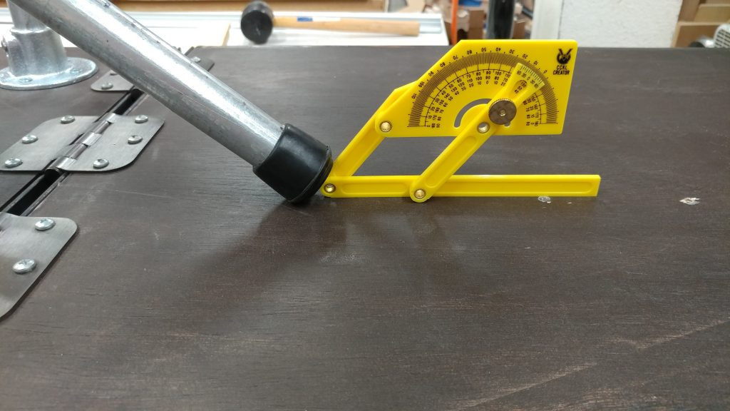
Since I didn’t tighten the set screws that hold the extension wing horizontal brace to the front and rear legs, this whole mechanism can swing up and support the wing. I needed to make a wedge for the leg to press against. After ensuring that the bench-top pieces were co-planar, I swung the arm down and measured the angle.
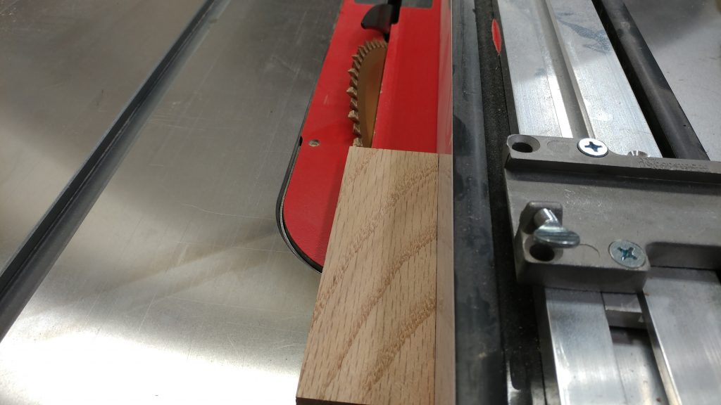
I then transferred that angle to the table saw.
I cut a bevel of that angle on a scrap piece of oak flooring that was left over from this same project. I left this piece longer than I needed in case I need to try attaching it in different areas.
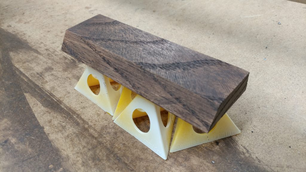
Once it was cut, I applied a coat of the same stain that I used on the rest of the desk and a single coat of polyurethane.
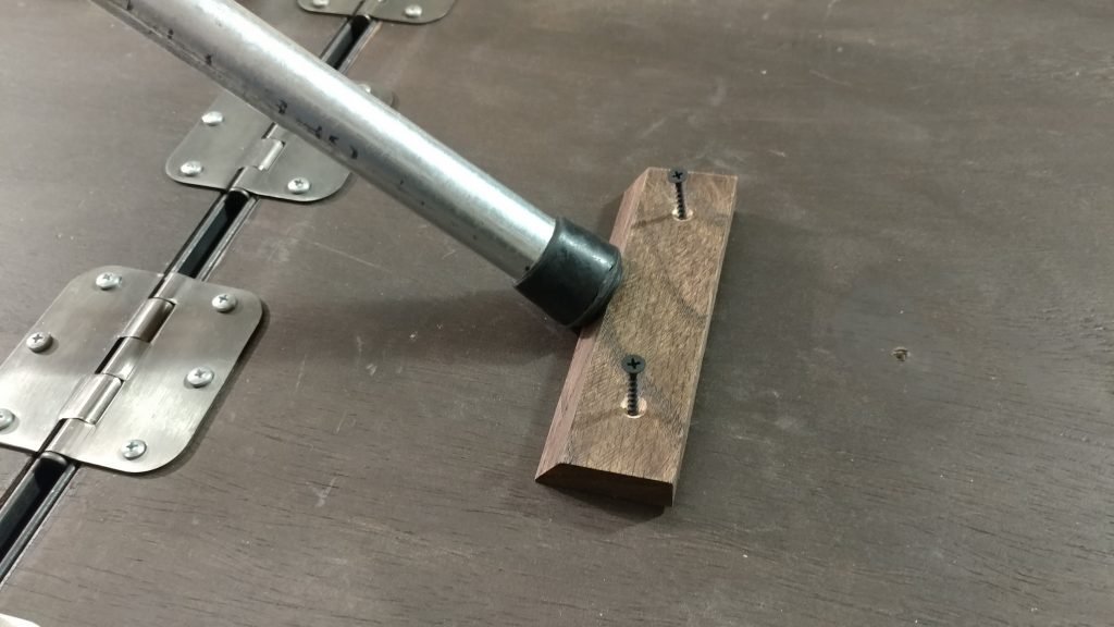
I pressed this piece firmly into the foot of the extension wing arm and secured it with drywall screws. I didn’t glue it in case I wanted to make any adjustments.
I set the bench upright and tested it out. The wing sagged a bit but rather than remove the wooden wedge and move it forward, I loosened the set screw that holds this arm in place and slightly extended the arm a bit. I tightened the set screw again and made sure the wing was flat with the main table.
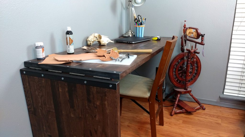
If you want to lower the extension wing, you simply lift the extension wing slightly and the support arm swings down out of the way. The rubber foot on the end grabs the bottom brace and friction locks it in place.
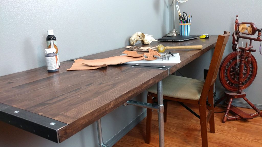
All finished.
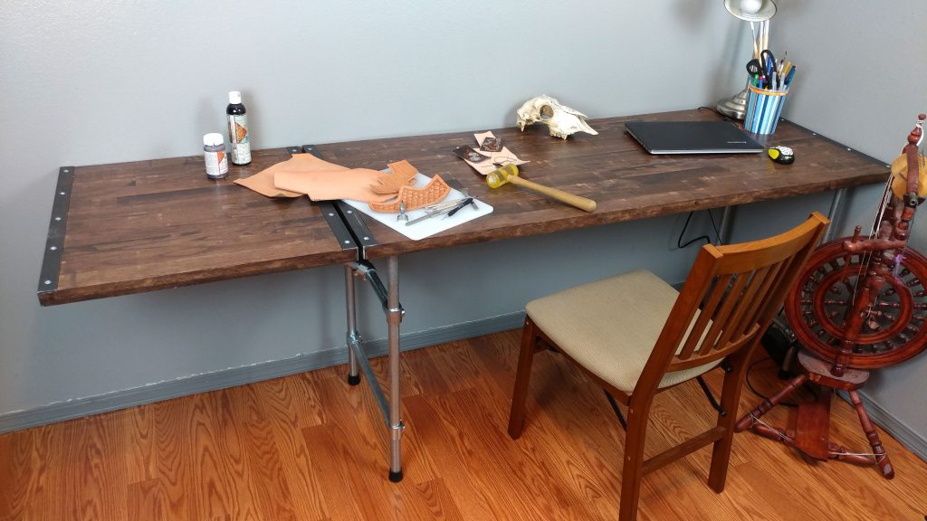
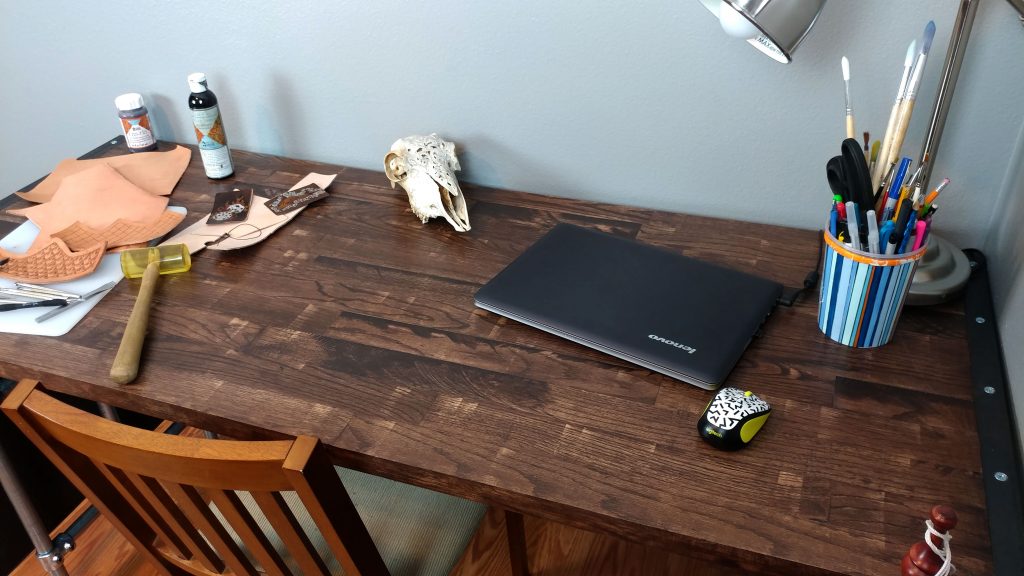
It’s time to call this project done. My wife and I moved it up to her studio and I gave her a few days to test it out. So far it seems to be very sturdy. I have plans to add a shallow drawer or two but I’m going to let her use the bench for a bit to see if that is something that she really needs.
It really does provide a lot of work surface. The overall dimensions of the work surface is 24 ½” x 83 ¼” when the extension wing is up.
When the extension wing is not needed, it easily folds out of the way creating a work surface of 24 ½” x 60 ¼”.
This gives her the space to work on her computer while still having her projects set up.
Please let me know if this helped you in any way or if you have any suggestions for how I could have done this differently. I’m also planning on a few more projects along this same style so if you have any suggestions, please let us know in the comments section below. I’d love to hear from you. Also, please consider signing up for my mailing list to be notified of future articles. I am also available on social media. Stop by and say ‘Hi’. I can be reached at the links to the right.
<< Back to Workbench: Part 6 – Finishing the benchtop
<< Back to Workbench: Part 5 – Cutting the benchtop to size
<< Back to Workbench: Part 4 – Gluing up the new top
<< Back to Workbench: Part 3 – Change of plans
<< Back to Workbench: Part 2 – Gluing up the top
<< Back to Workbench: Part 1 – Milling down some 2 x 4s

