
A while back I converted my side extension table into a router table. Although not strictly necessary, I am going to enclose the router and add dust collection, while also creating much-needed storage and enclosing the electrical.
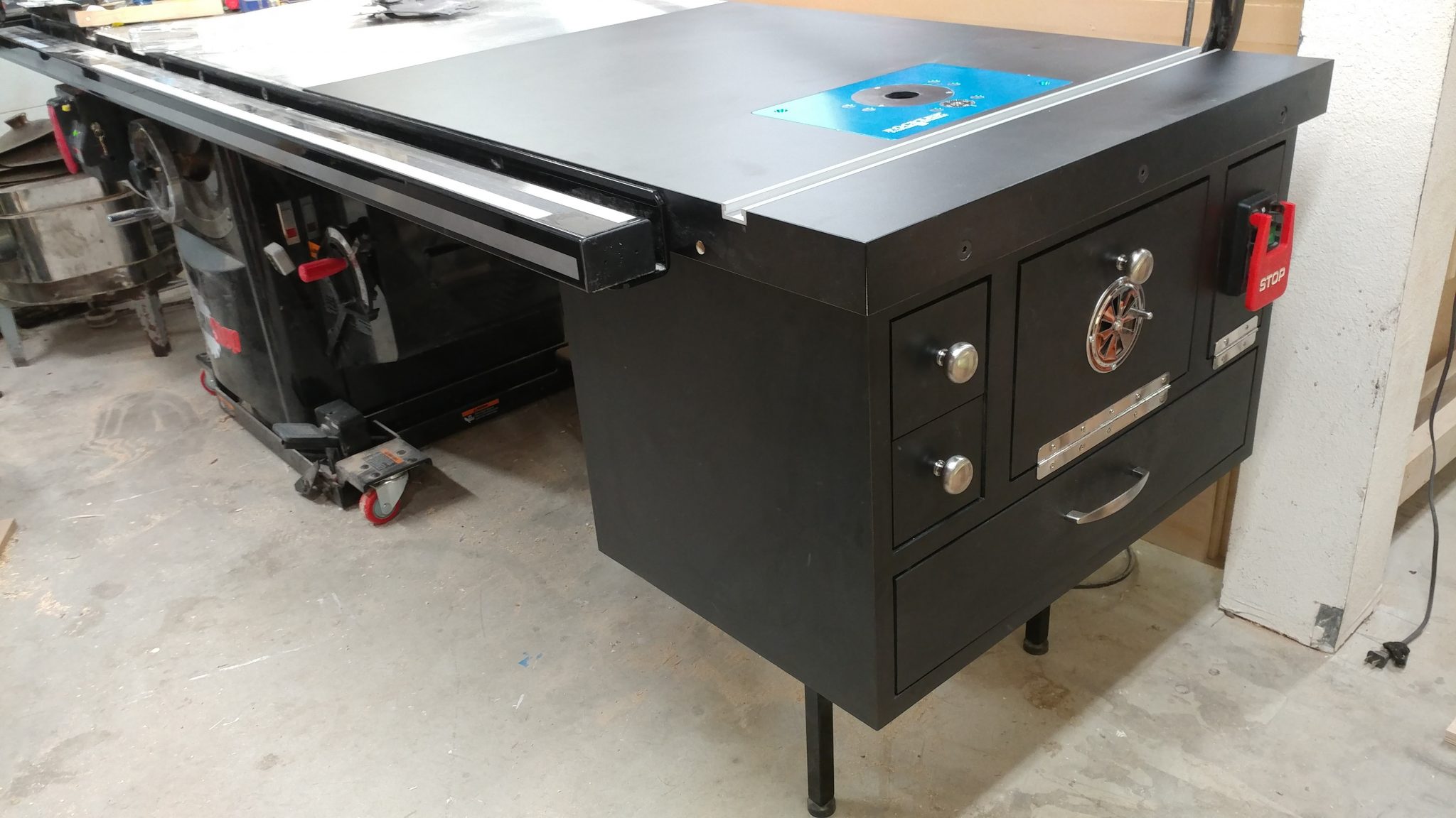
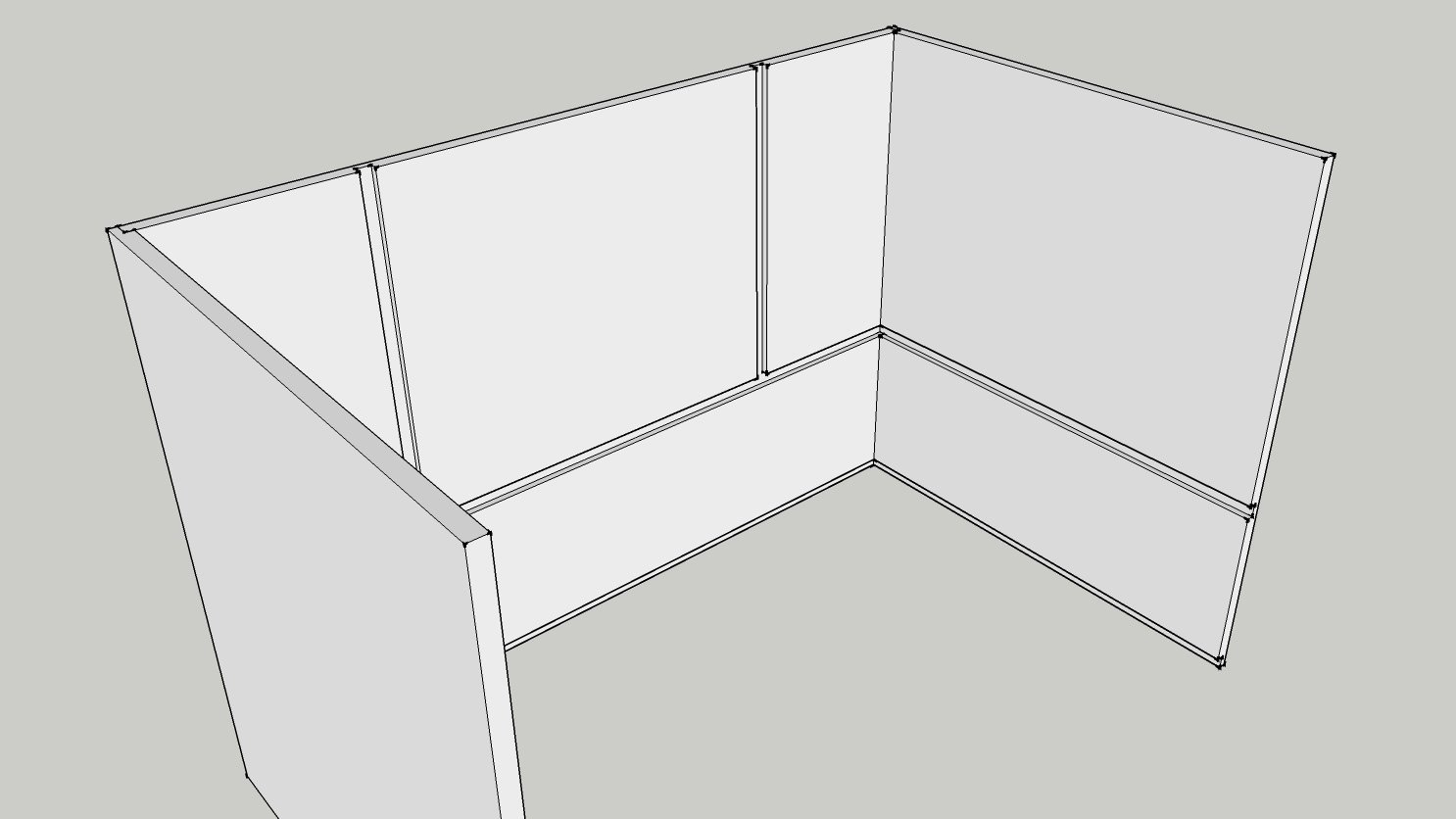
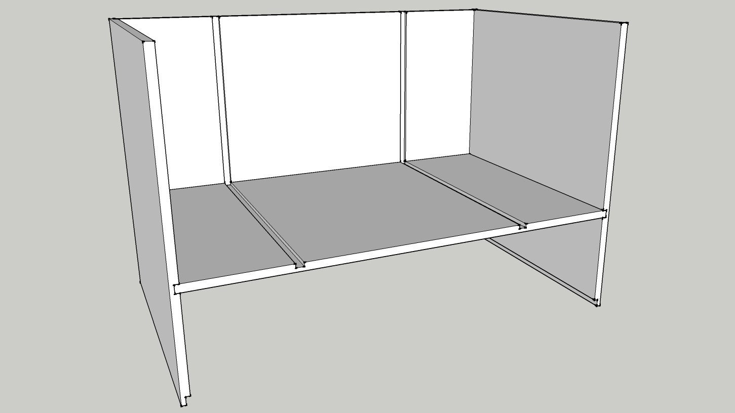
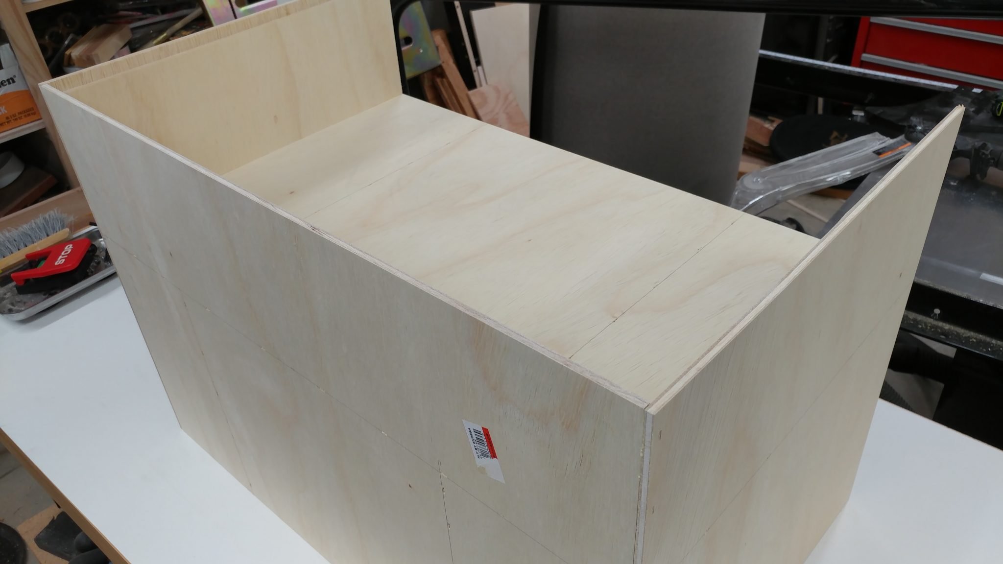
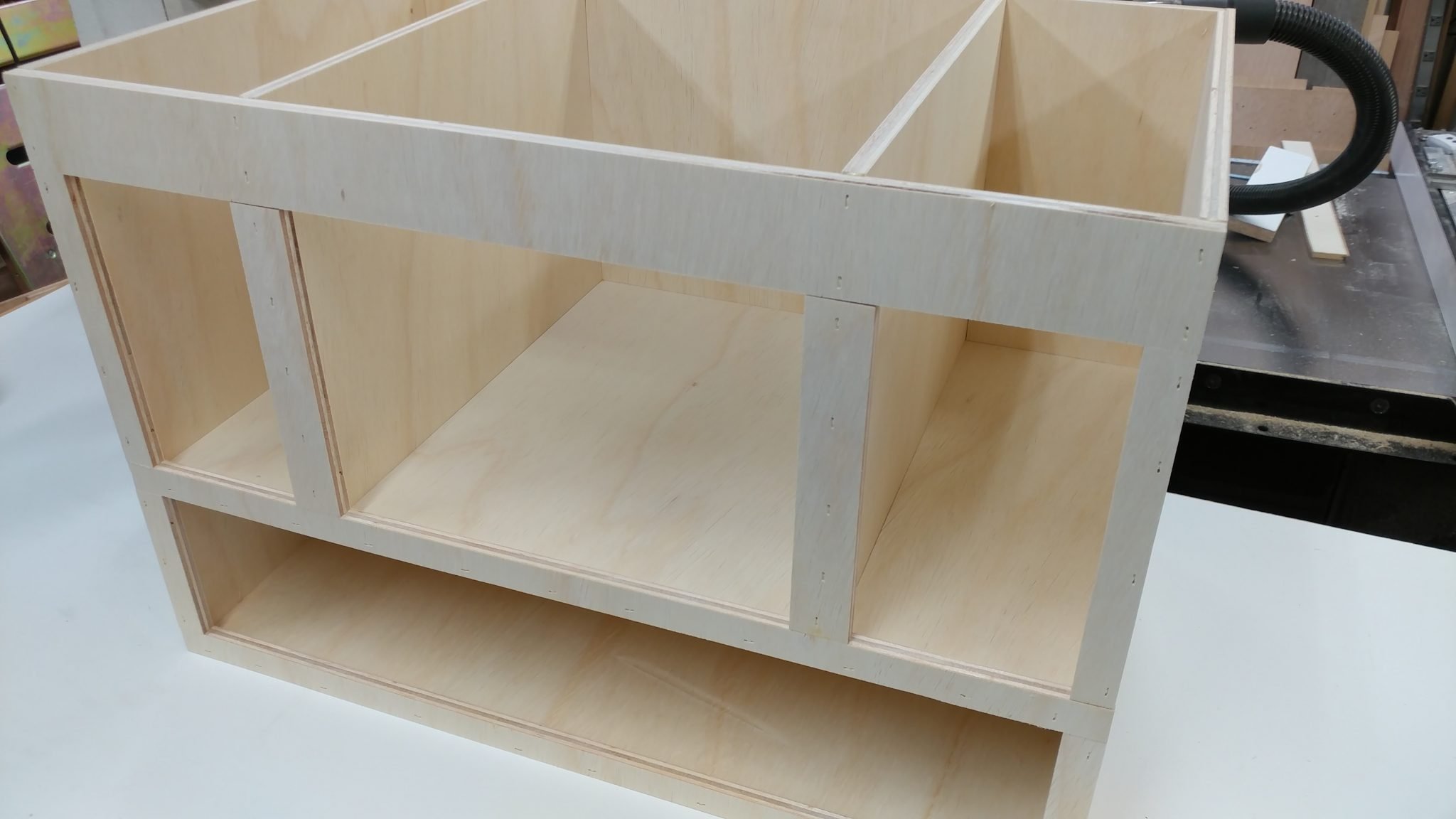
So you can see what I have in mind, here’s a sneak peek of the finished enclosure.
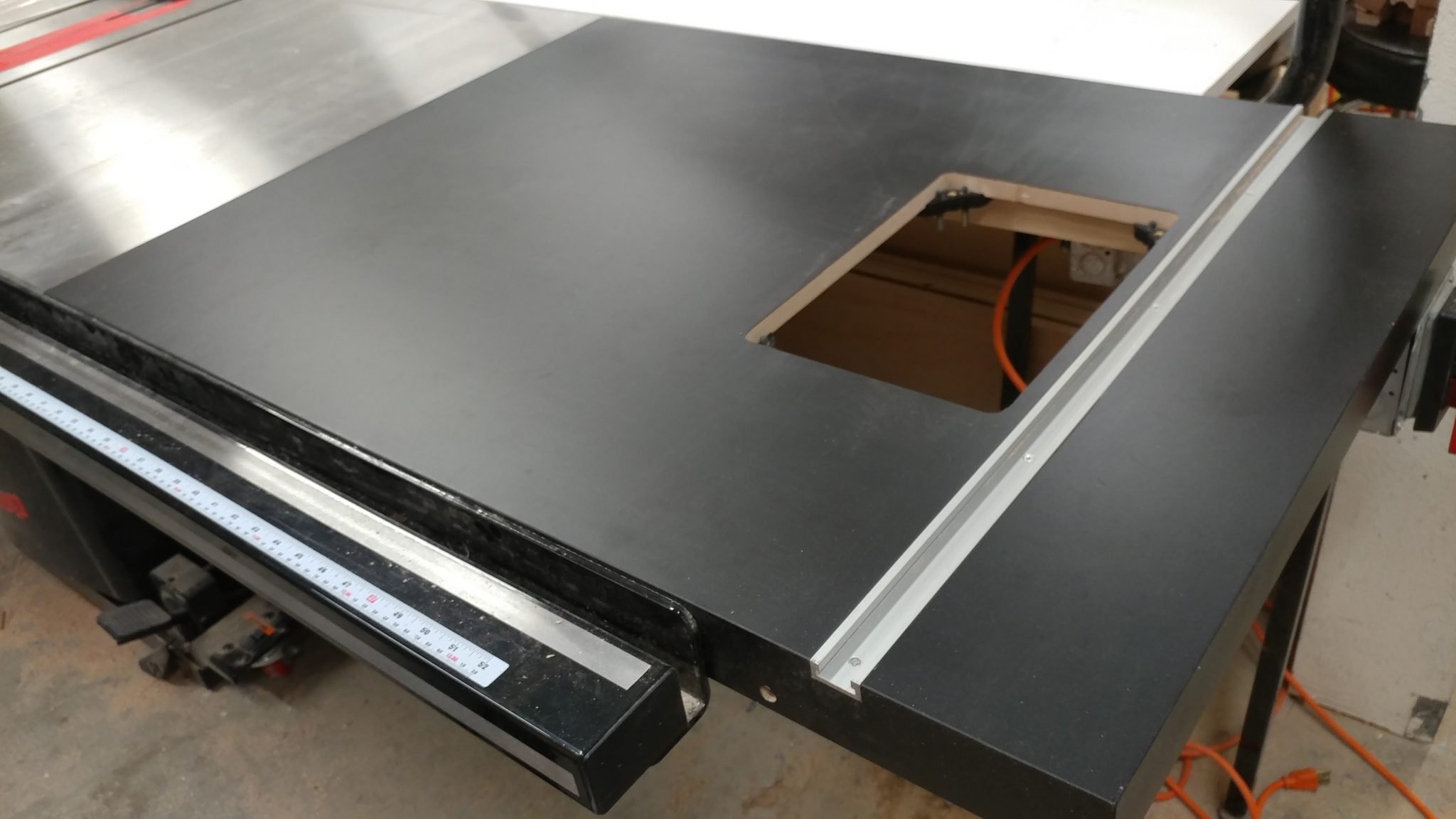
Preparing the table
To start with, I removed the router lift and detached the extension table from the saw.
Once the table is turned upside down, you can see that I will need to remove the wooden bracing, both legs, and the electrical hookups in order to accommodate the new enclosure.
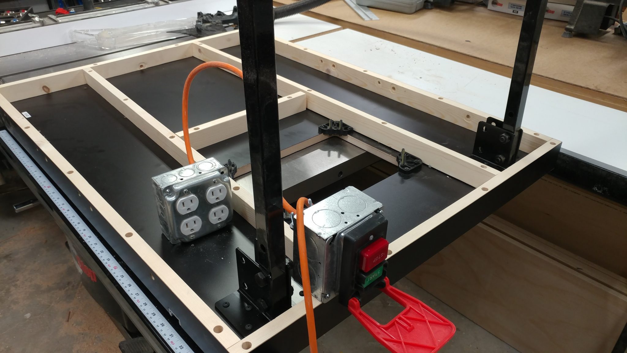
I removed all of that but decided to keep the router lift supports since they shouldn’t interfere with the new enclosure.
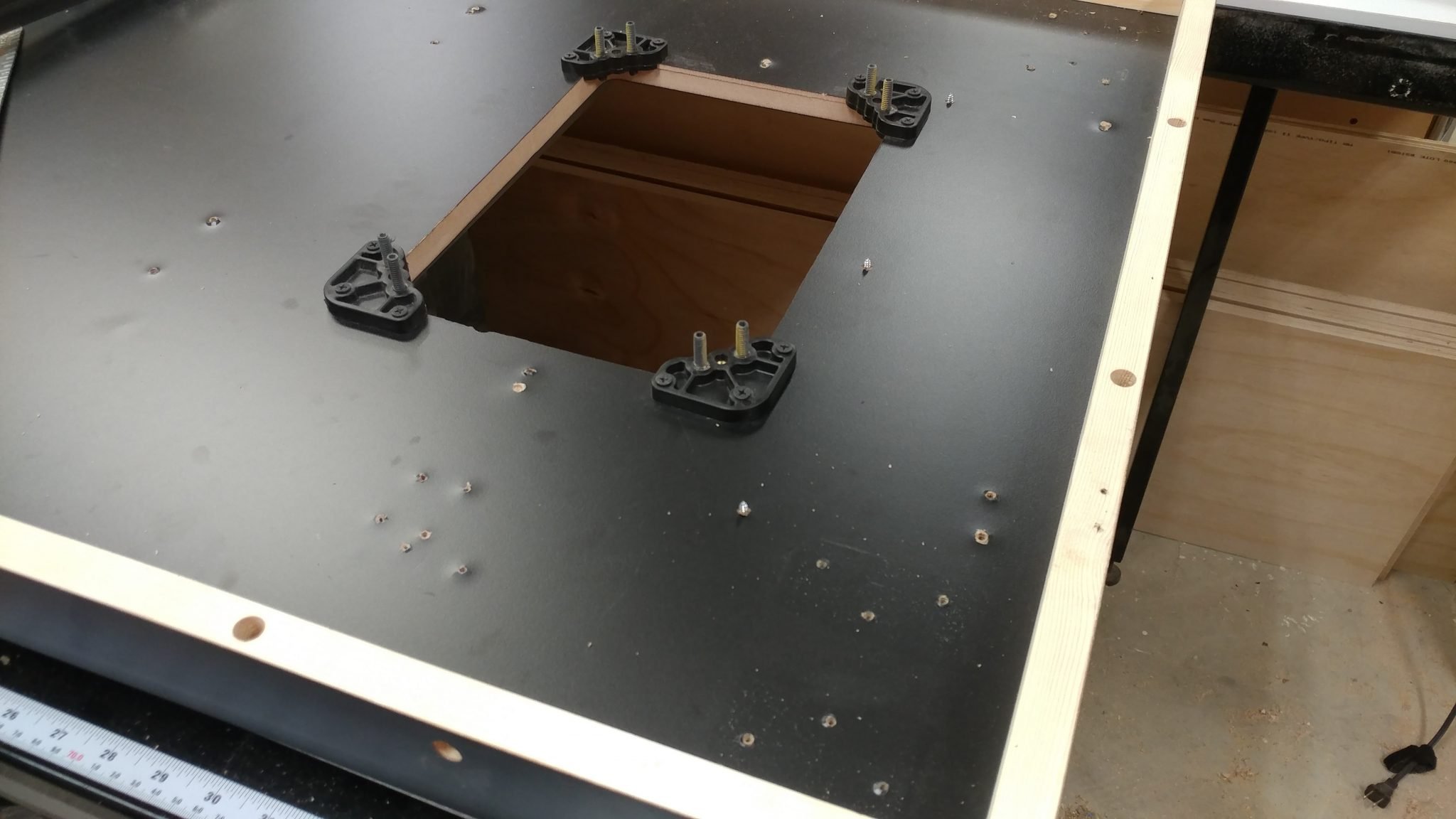
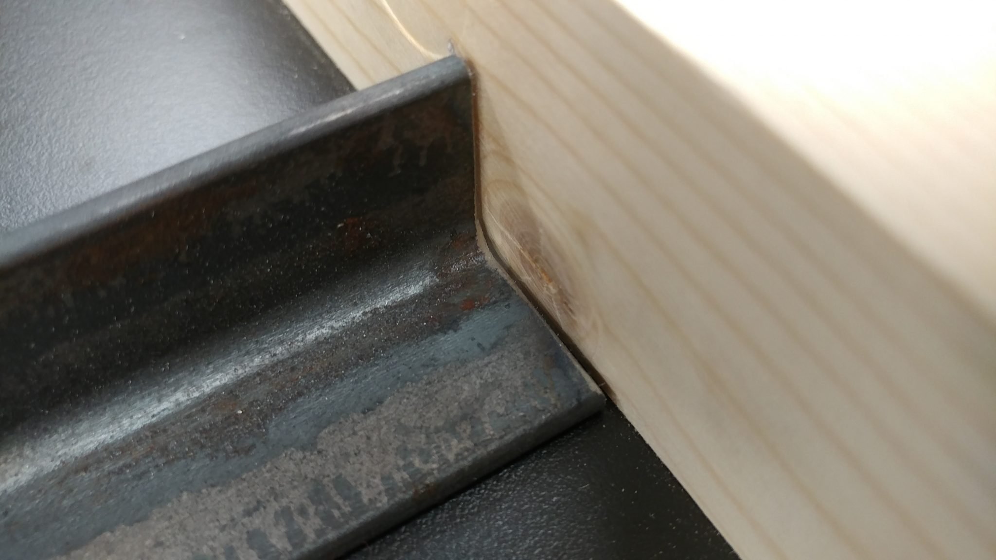
One of the things I wanted to accomplish with this was to beef up the bracing under the table. I don’t think that the wooden bracing that came with the table was doing much to prevent sagging from the added weight of the router lift since it mainly runs from left to right. I decided to run a piece of angle iron from front to back that I will use to not only support the table but attach the router enclosure to. The inside area of the table measures just under 28 3/8″ I’ve decided to make a cabinet that is 28 1/4″ wide.
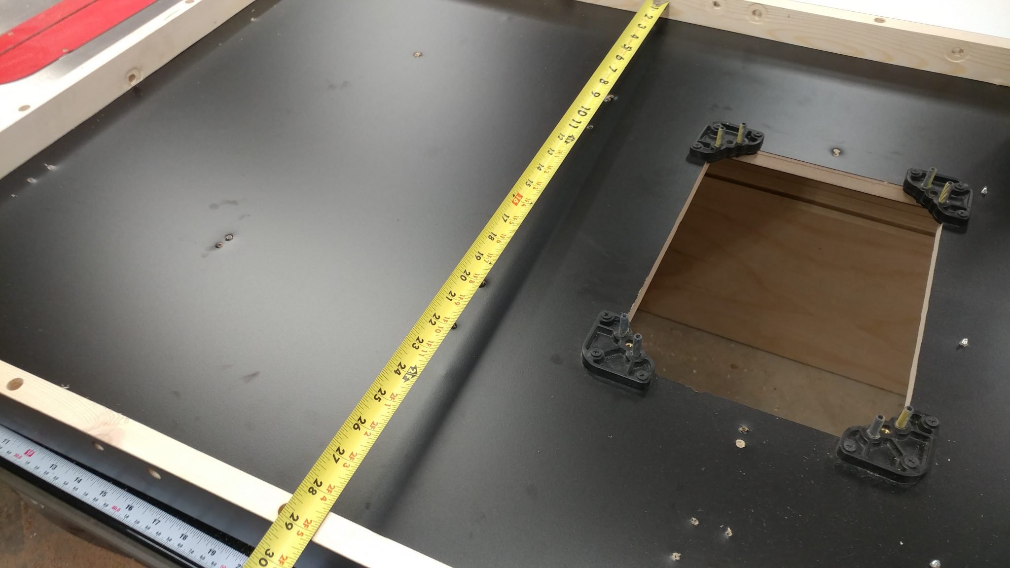
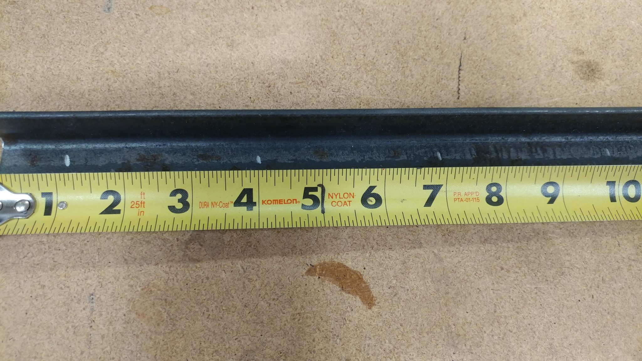
I cut a piece of 1″ angle iron to ~28 3/8″.
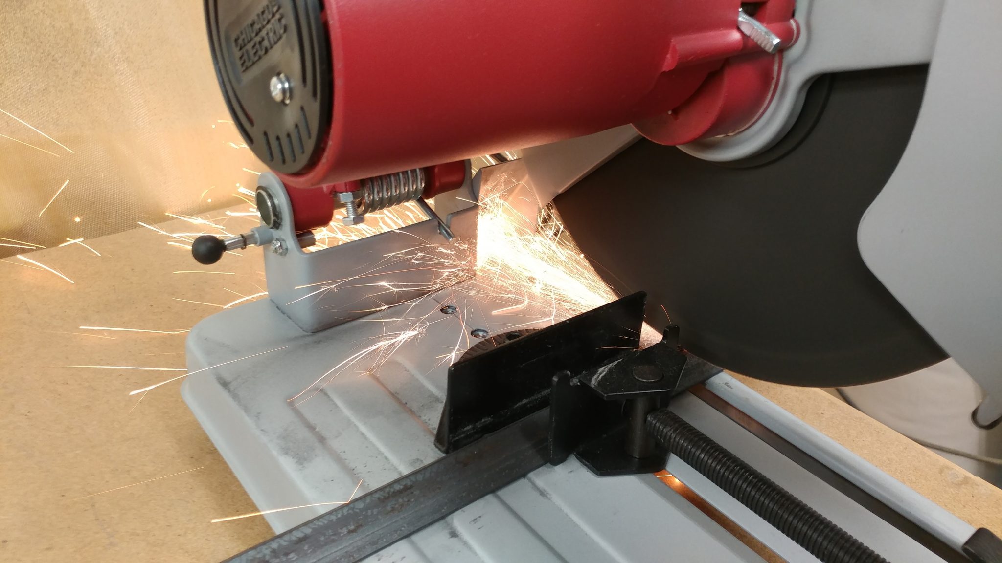
The chop saw leaves a pretty nasty burr which I removed with a flat file.
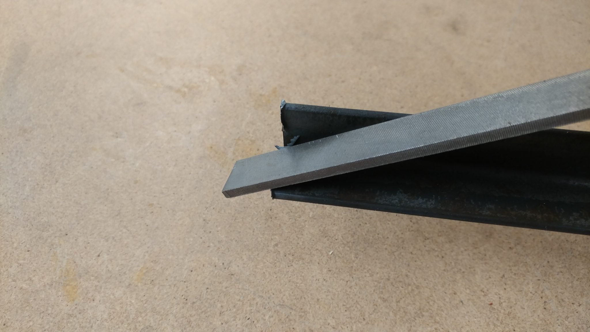
The piece fits nicely between the front and rear edge of the table.
The screws that I’m using to attach the angle iron to the table will need to be 3/16″ wide to accommodate the screws.
Using a silver Sharpie, I made marks on the angle iron about 3″ apart.
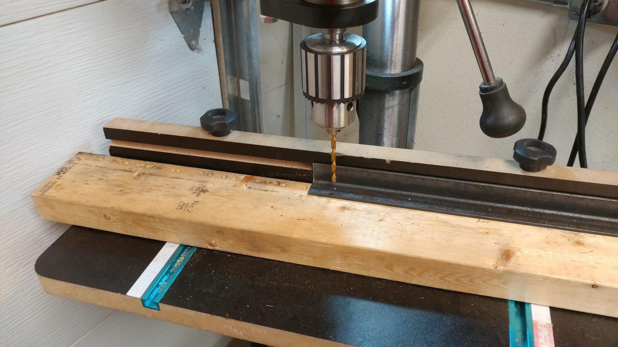
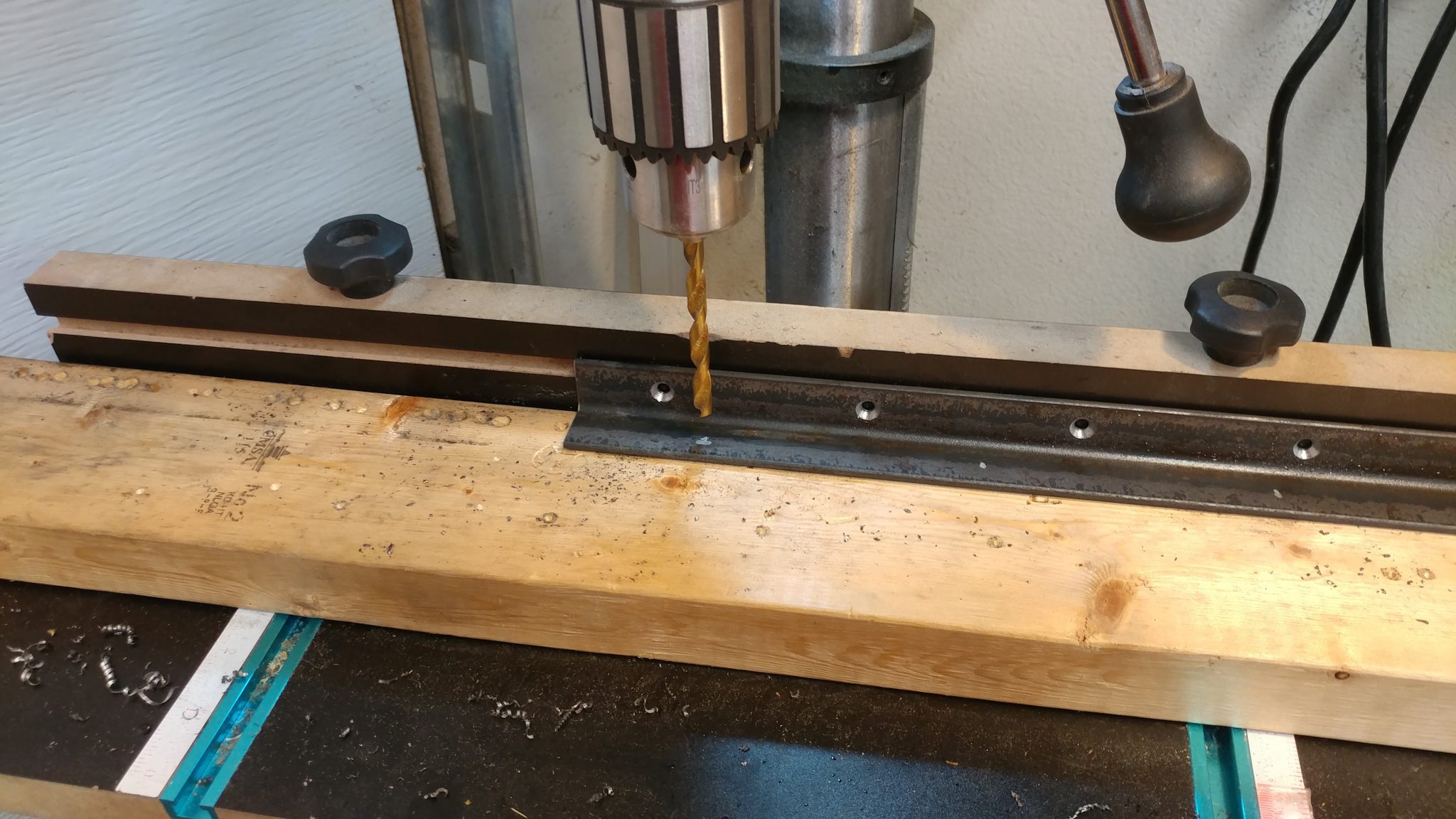
Using my drill press, I installed a 3/16″ bit and used some 3-in-1 oil to drill each of the holes.
I added a countersink to each hole so the screws sit flush
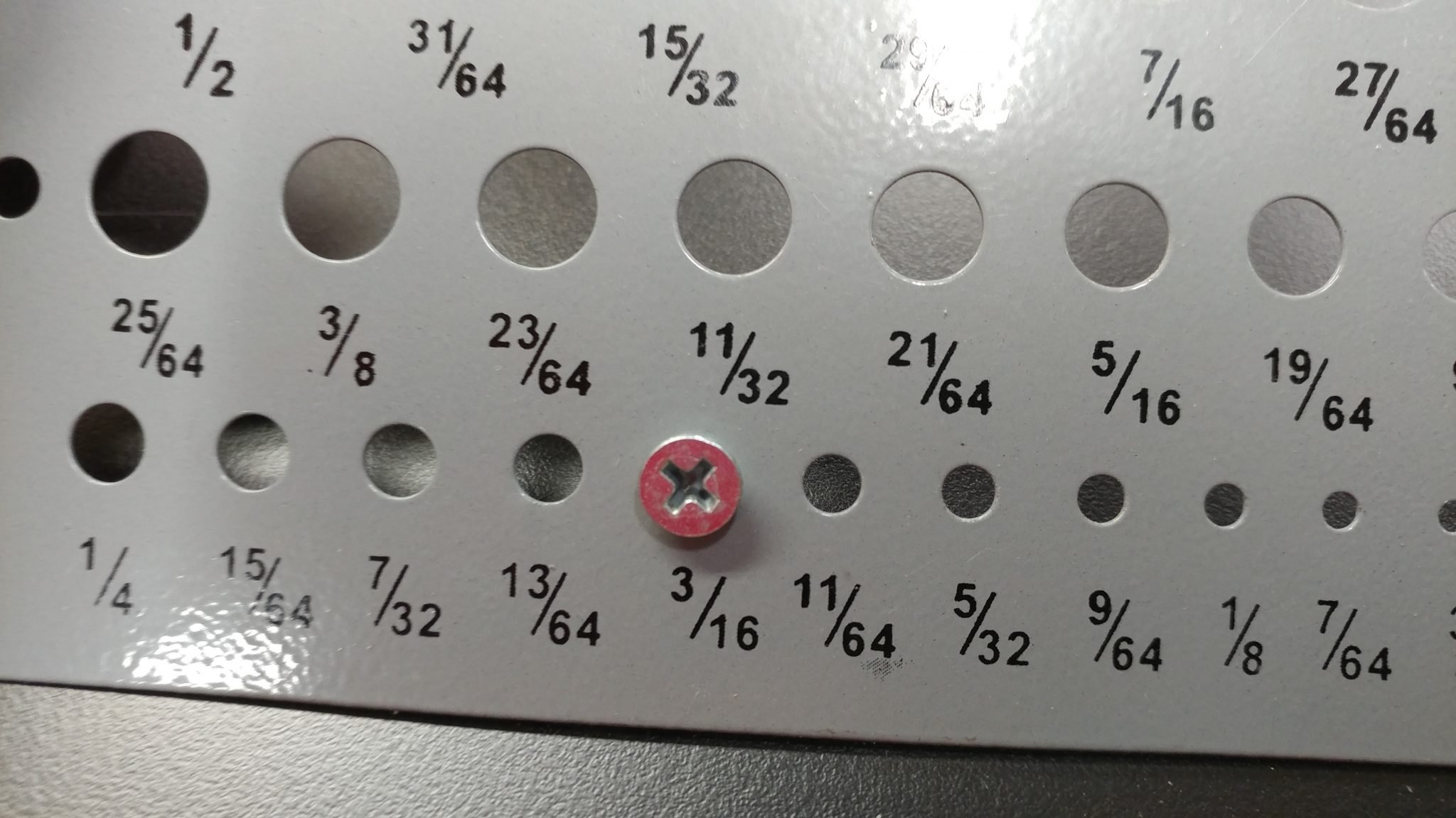
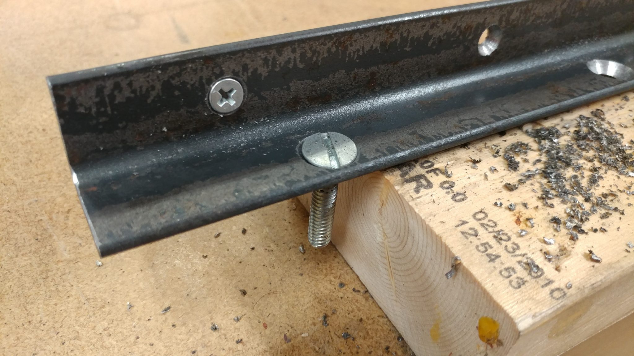
Scrounging through my coffee can of miscellaneous hardware, I was able to find some countersink bolts that match up with the 1/4 – 20 tee nuts that I had. I will use these to attach the cabinet to the angle iron.
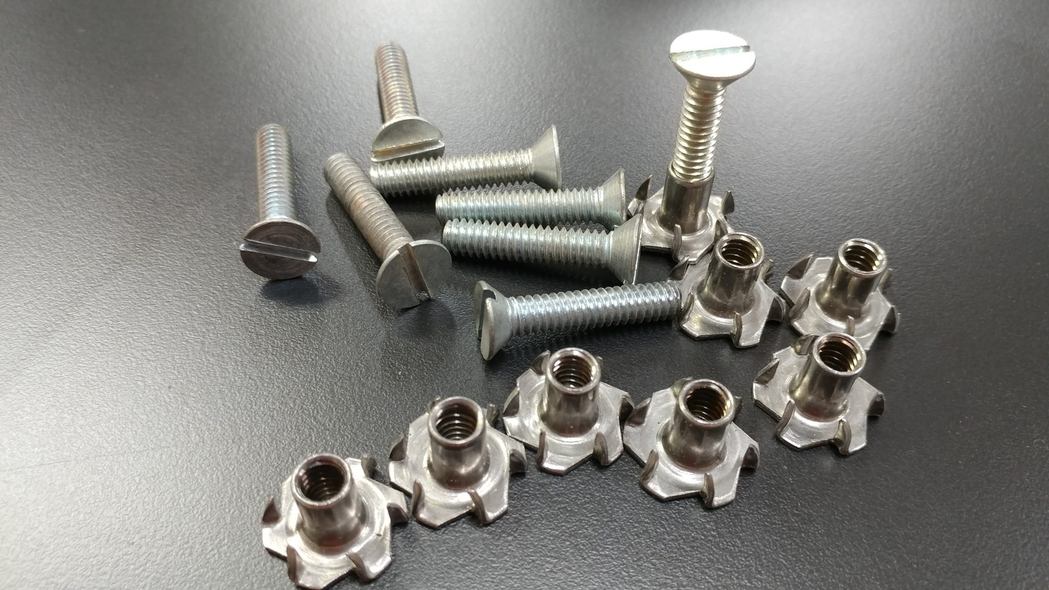
The bolts require a hole that is 17/64″ in diameter.
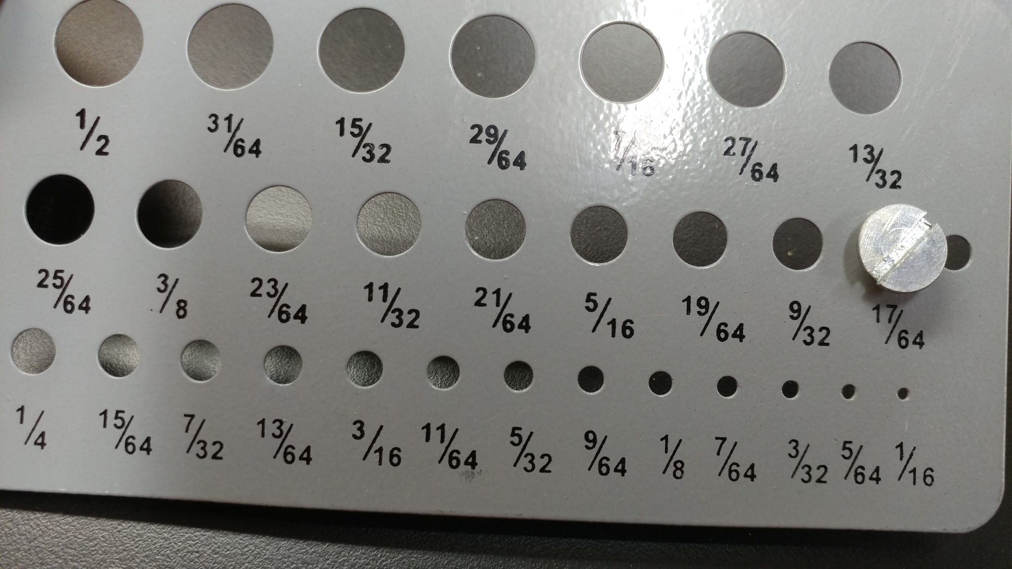
I laid out where I am going to drill the holes about 4″ apart.
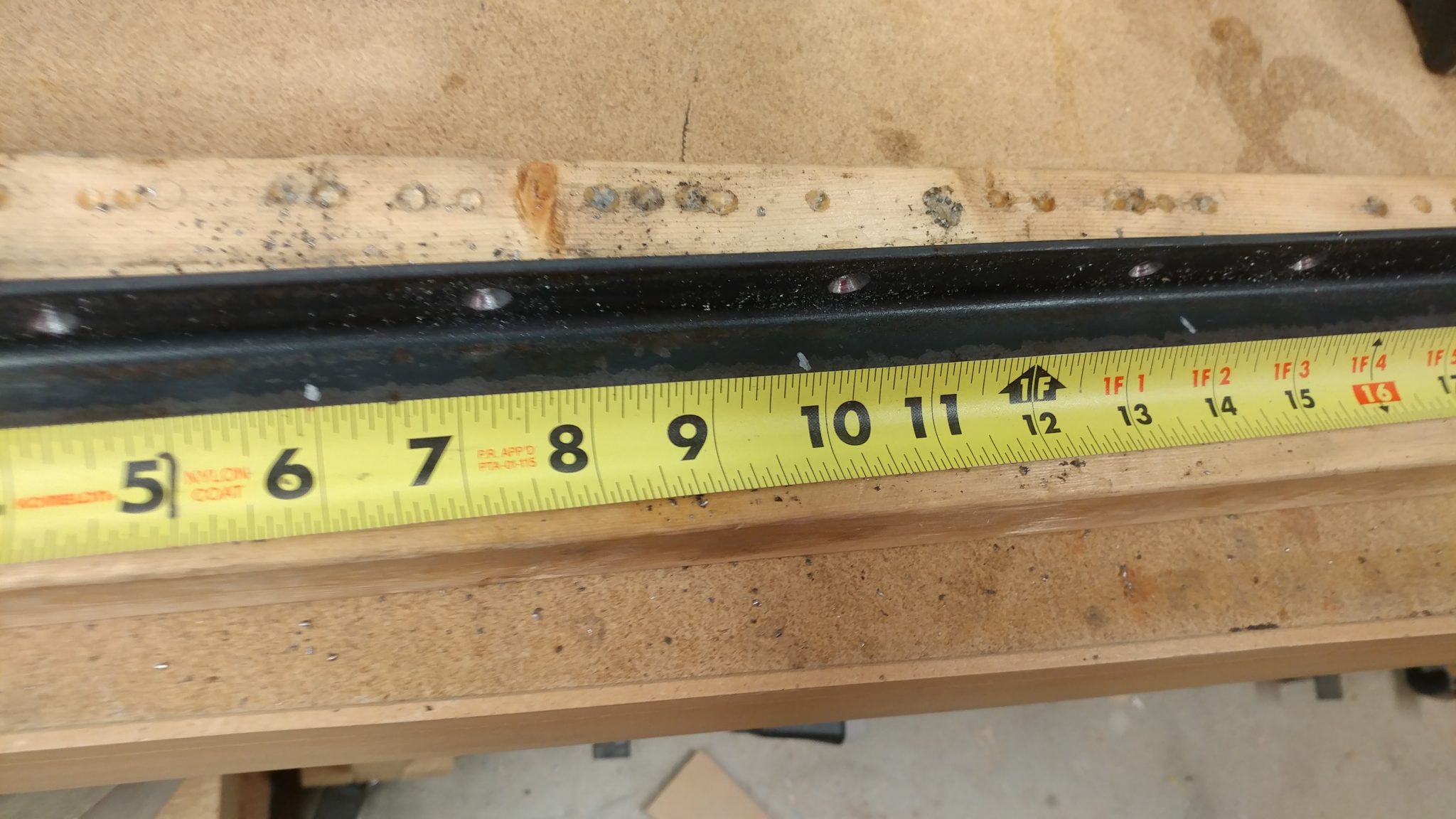
I installed a 17/64″ bit in my drill press and using some 3-in-1 oil, I made the holes.
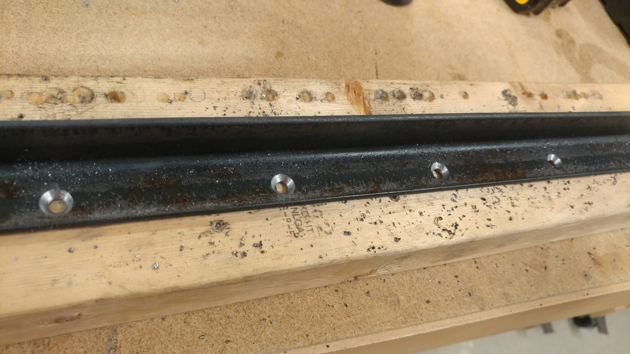
I added a countersink to each of the holes so the bolts sit flush with the angle iron.
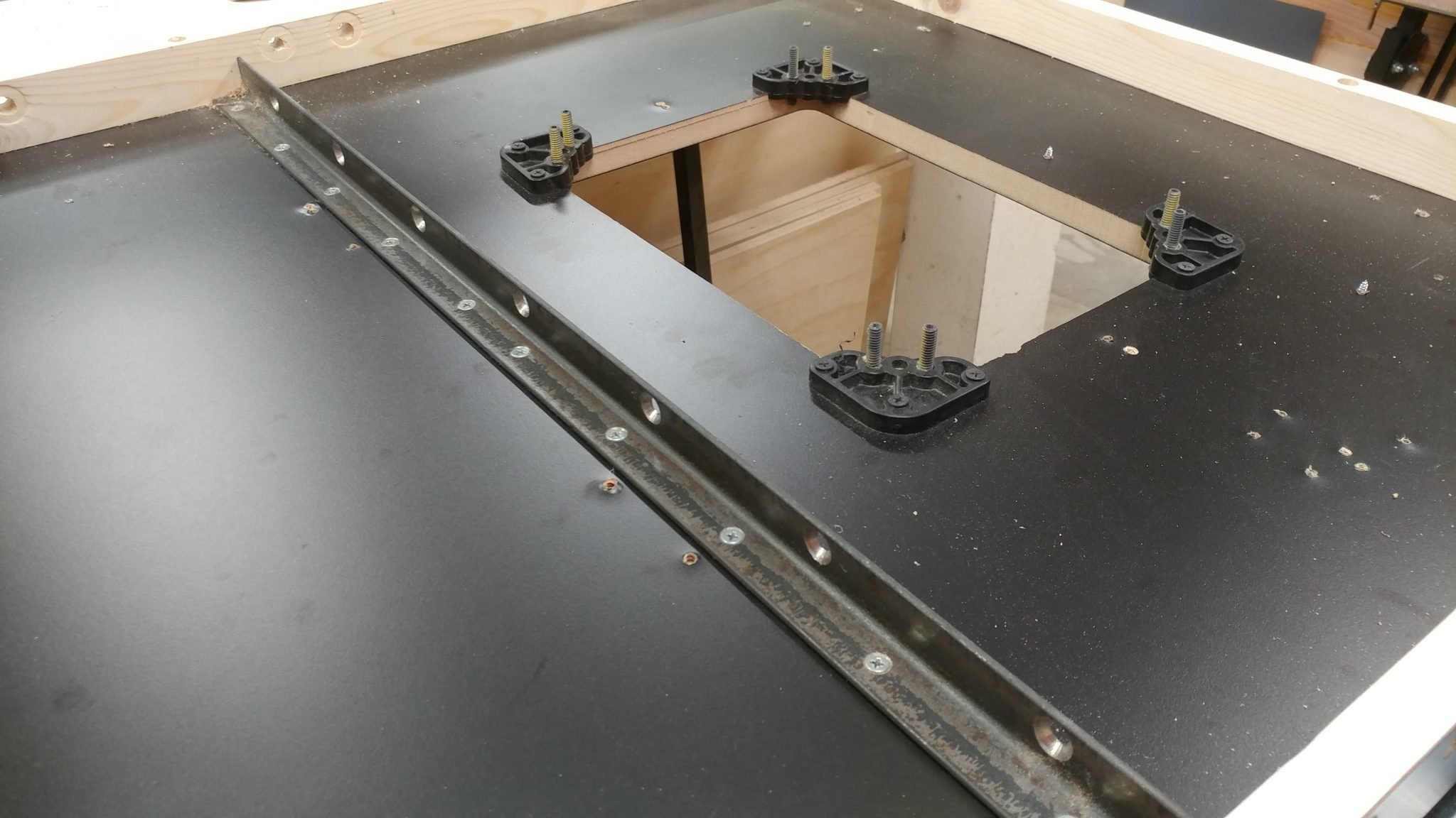
I decided to make the cabinet 18″ deep so I clamped some speed squares to the front and back walls of the underside of the extension table and positioned the angle iron making sure that the smaller holes are facing down.
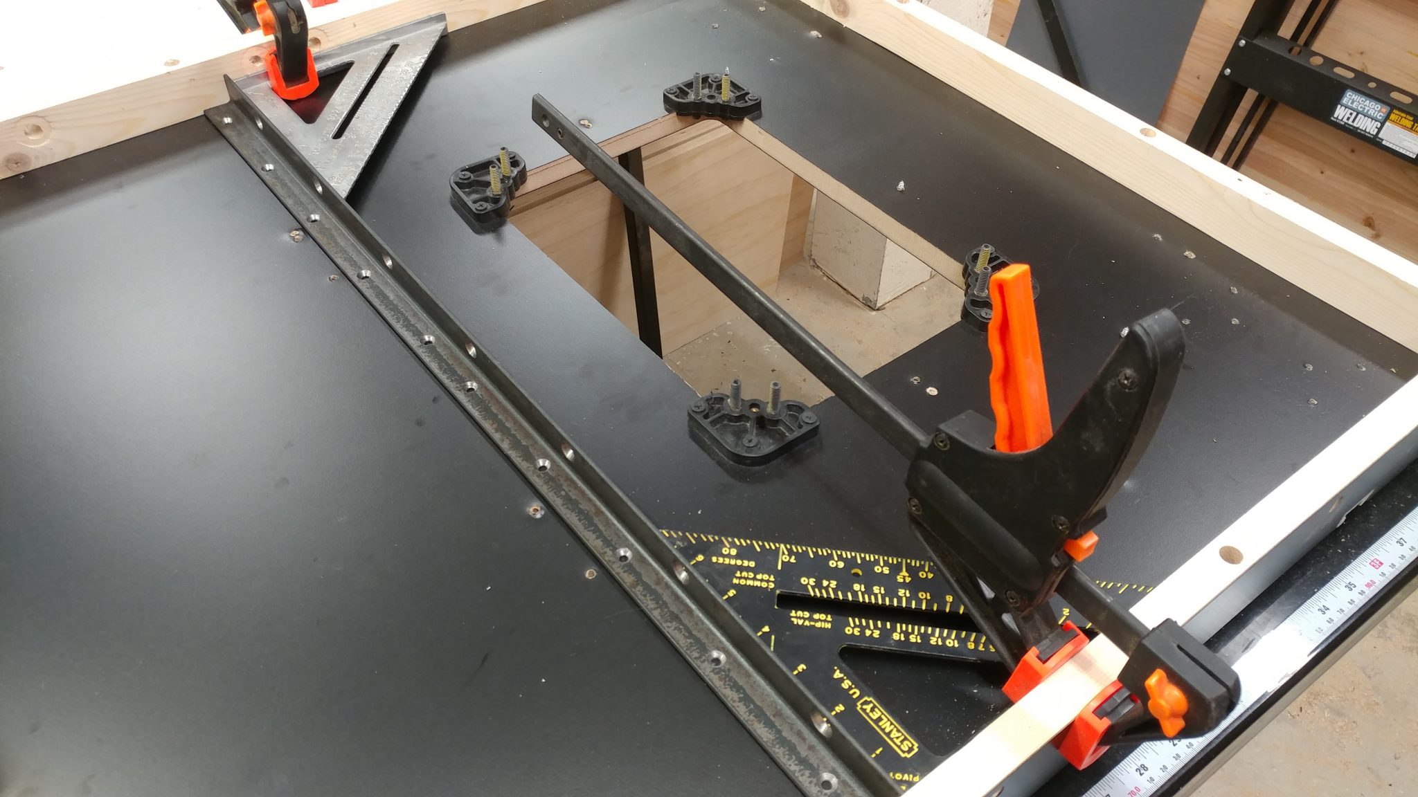
I attached the angle iron using the screws chosen for the job.
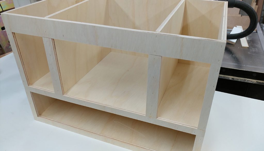
Assembling the cabinet carcase
The cabinet was originally going to be made from 3/4″ plywood that I had as scrap. I made a mock-up of it and quickly realized that it was going to be pretty heavy and unnecessarily bulky. I redesigned it in SketchUp out of 1/2″ plywood.
Before we continue, I am going to assume a few things about you, the reader, for the sake of brevity.
I am assuming that you are using a table saw that is 27″ deep. This is a fairly standard size for a 10″ table saw. My saw happens to be 30″ deep so the measurements I cut to most likely wouldn’t be appropriate for your saw. That being said, here are the outer dimensions of the router enclosure that I made. This is just to give a general idea of what I made and you can use it as a starting point for your enclosure.
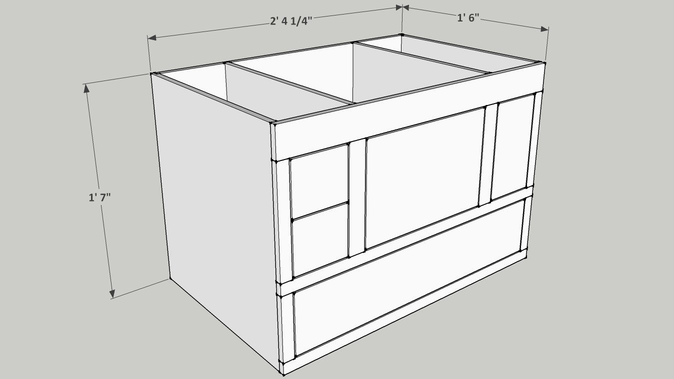
I’m also assuming that if you are interested in making a router enclosure for your table saw that you know how to cut plywood down to size. As such, I won’t go into great detail on how I cut each piece and what size I cut them to.
I will, however, cover a few things that may be of interest to you. Let’s get started…
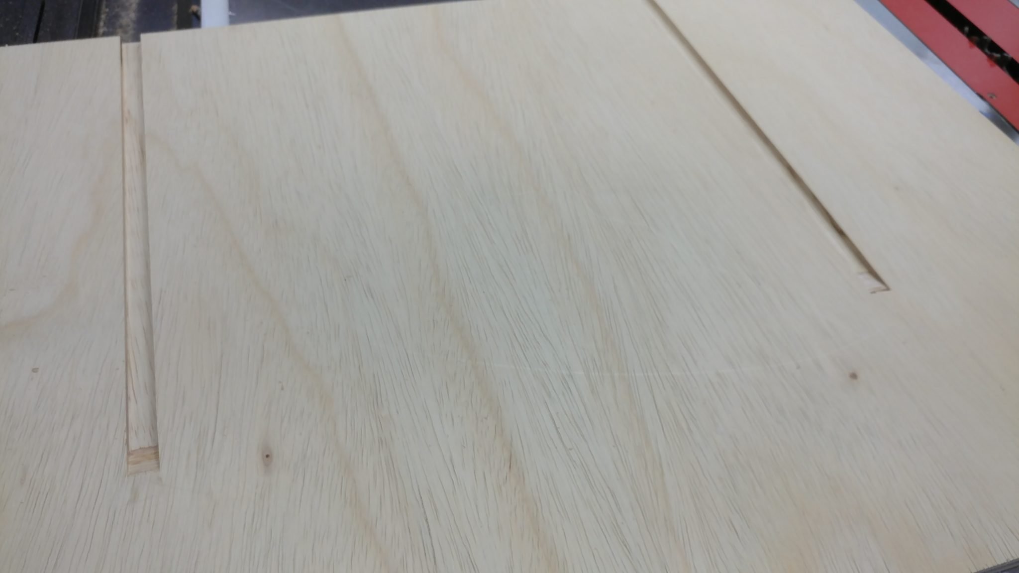
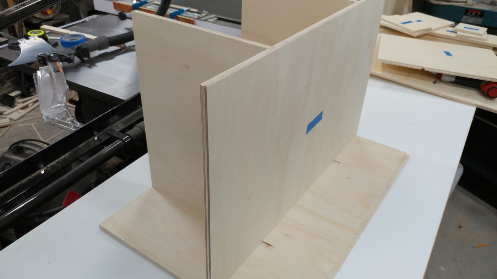
To put together the cabinet, I’ll need to make some dadoes and rabbets. For the two internal vertical walls I could just do full dadoes but I chose to do stopped dadoes instead. I don’t need them to be particularly neat as far as how they stop so I decide to just cut a dado and stop cutting at the dado that runs left to right.
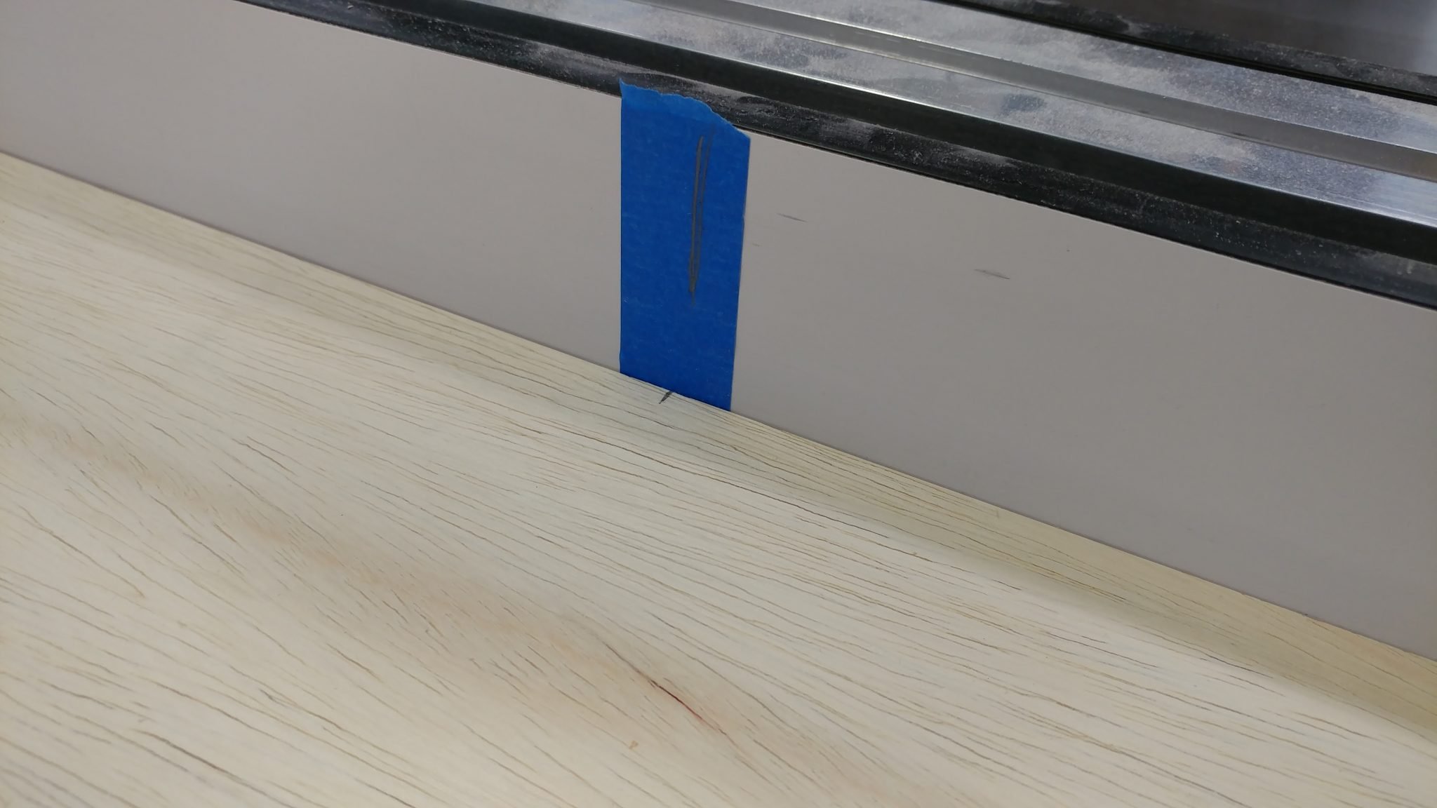
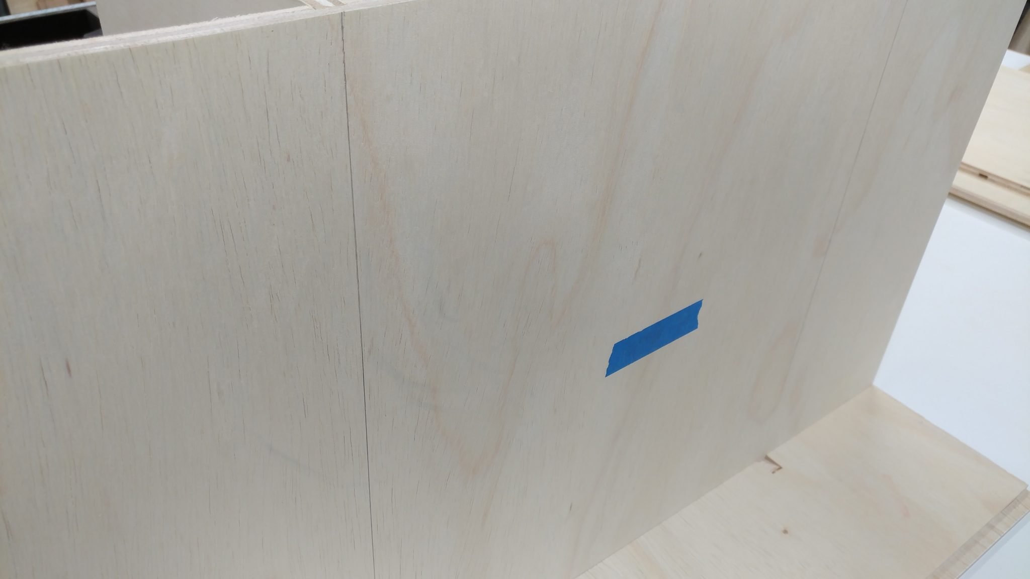
To set these up I made a mark on the board where the dado should end then put some blue painters tape on the fence and made a mark that lines up roughly with the center of the blade.
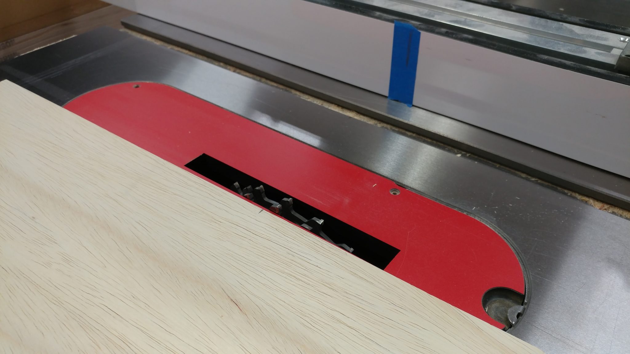
I push the material through and cut the dado. When the two marks meet up, I stop feeding the material and stop the saw.
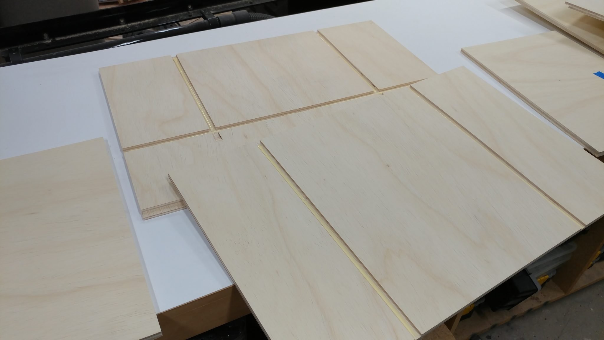
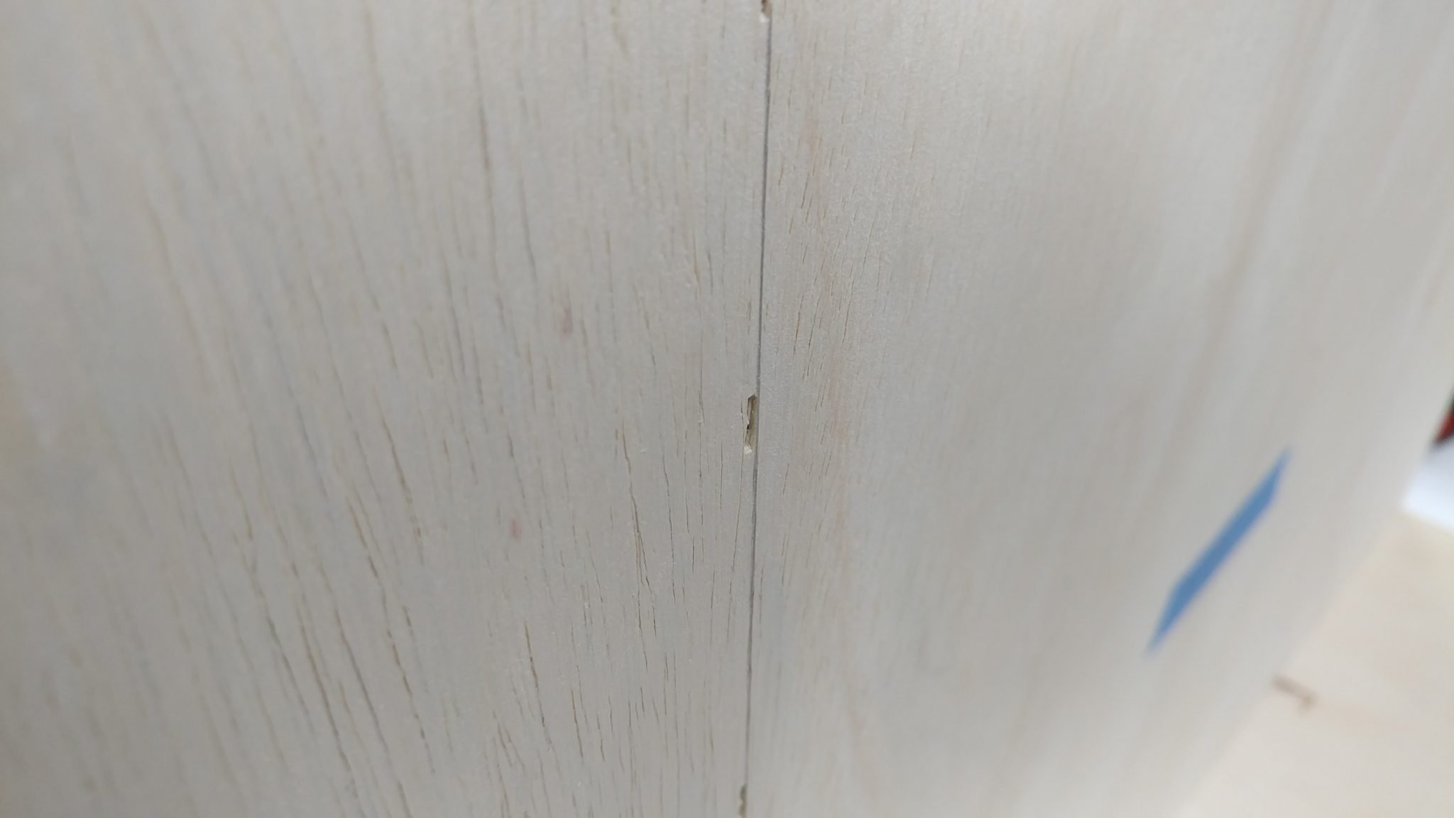
This results in a stopped dado. I make a second one for the other vertical wall.
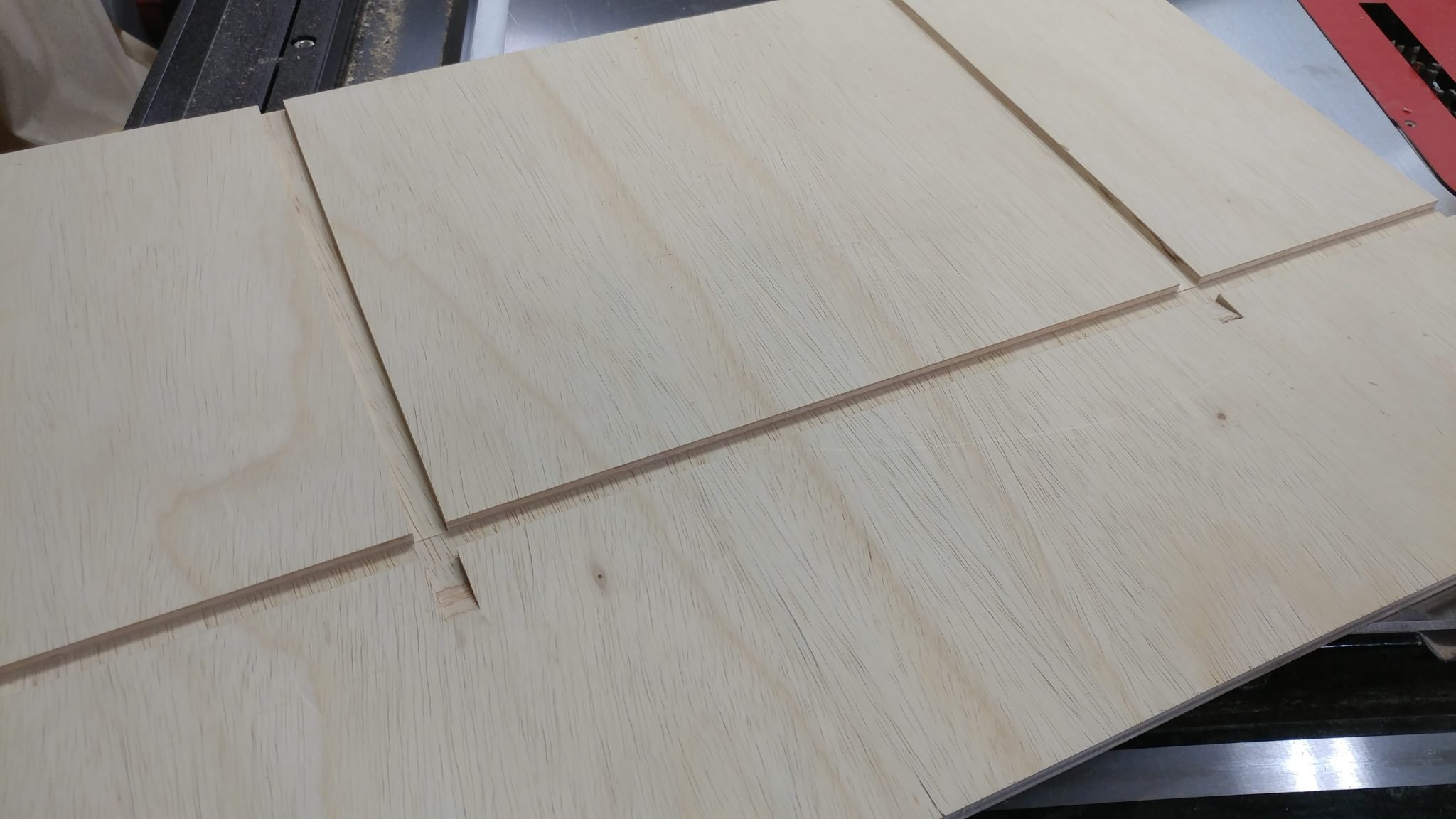
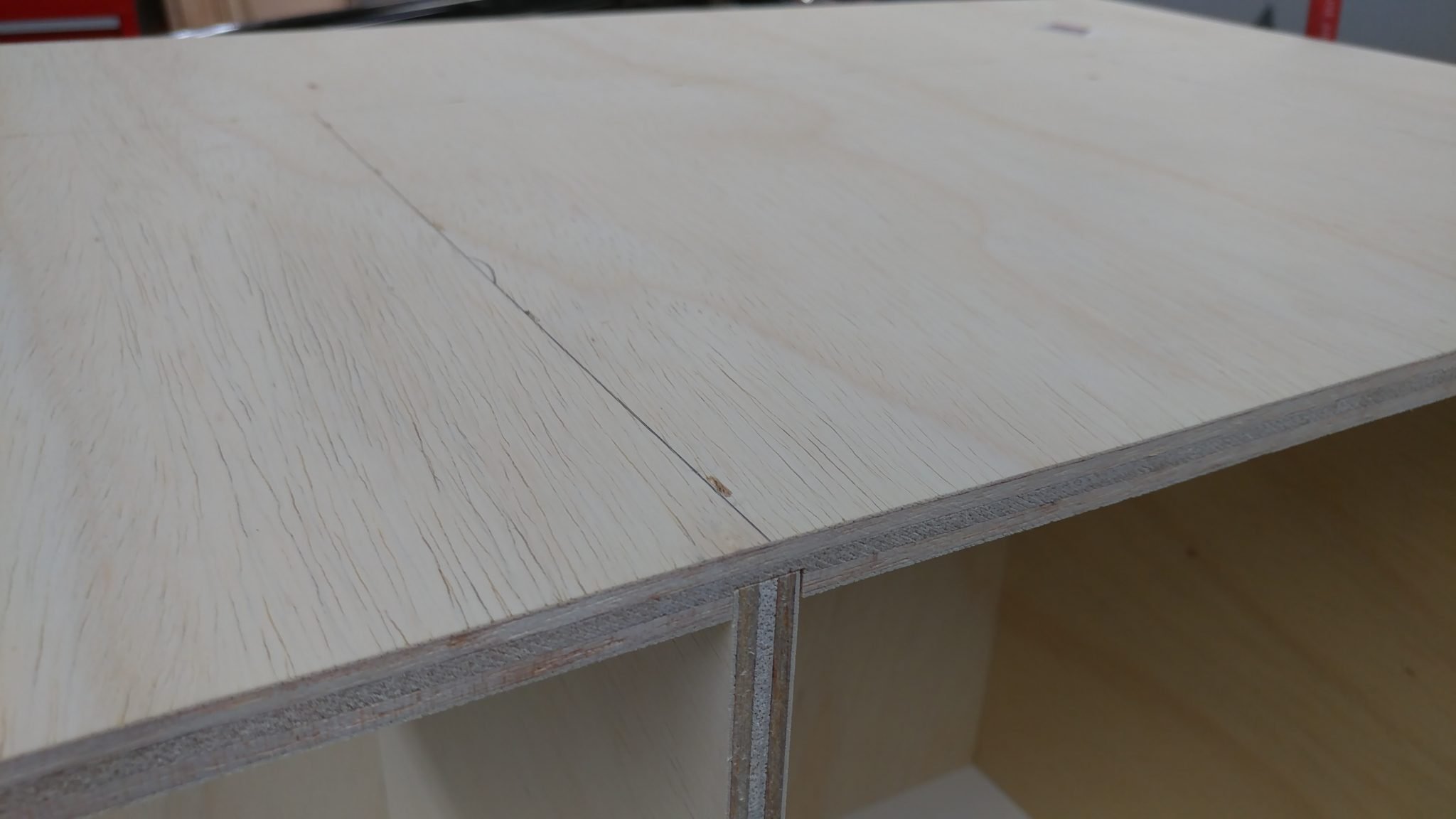
I then make a complete dado (technically a groove since it runs along the length of the material rather than the width) for the horizontal piece.
After I finish the dadoes, I need to make several rabbets on the edges of some of the workpieces. I set up a sacrificial fence and made all of the rabbets.

The back piece has a rabbet along the bottom edge.
The two side pieces will have rabbets along the bottom and back edges.
I cut the dadoes and rabbets on the side pieces.
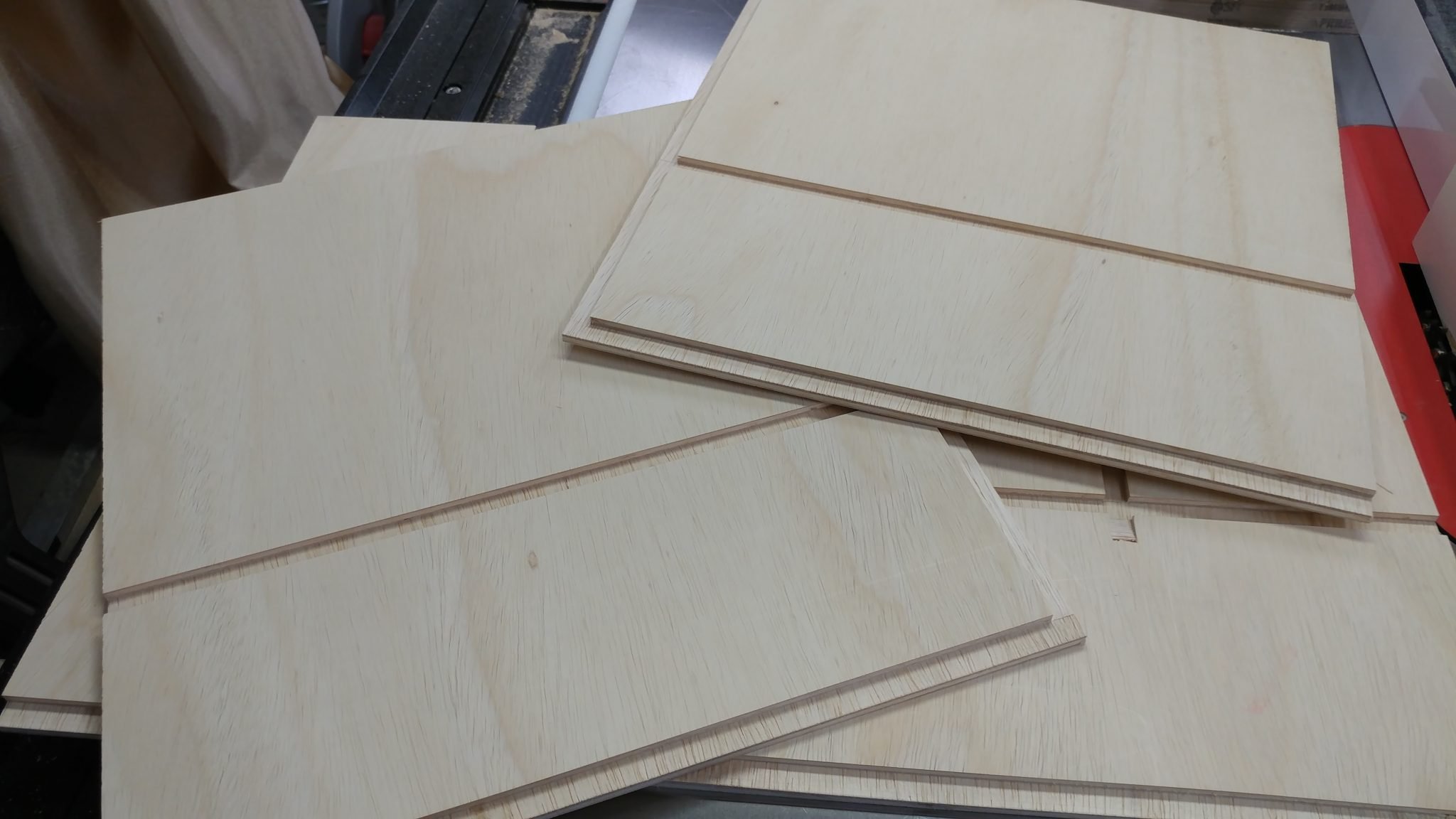
The horizontal piece has two dadoes that line up with the two stopped dadoes in the back piece. Other than the drawer (which I cover later) nothing else has any dadoes.
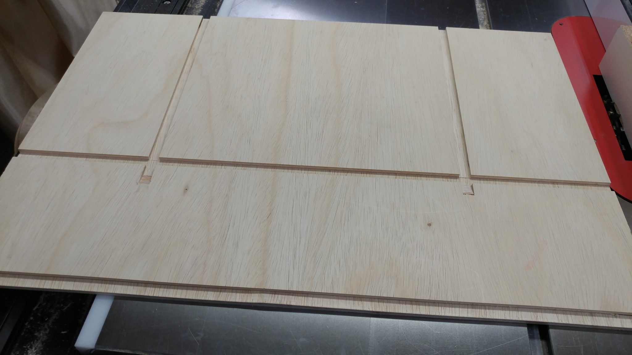
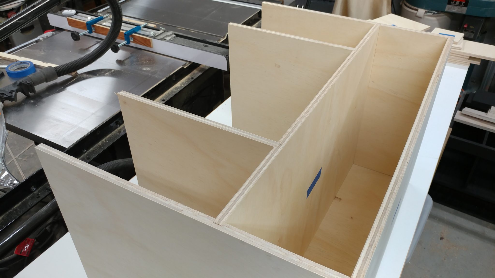
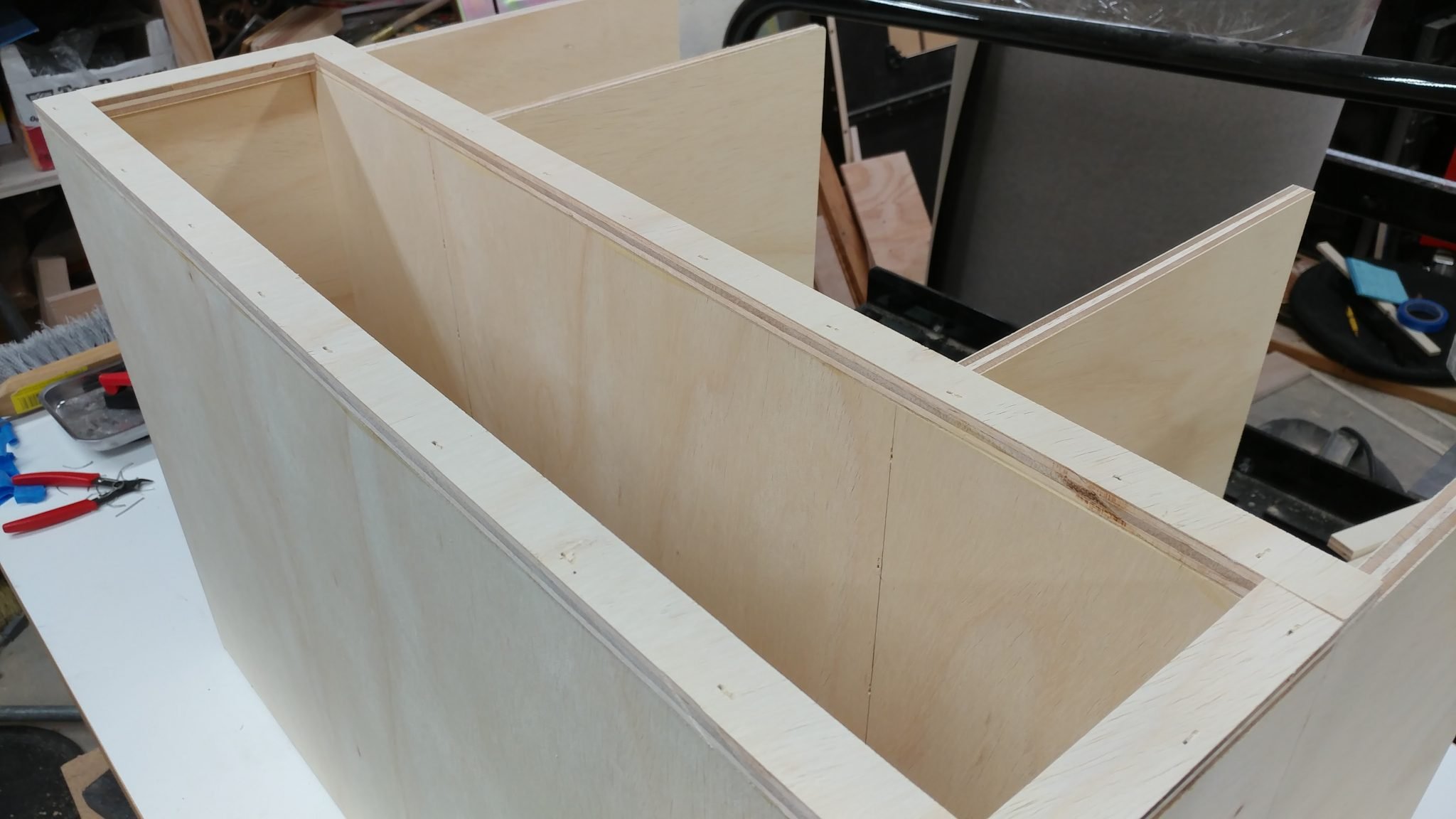
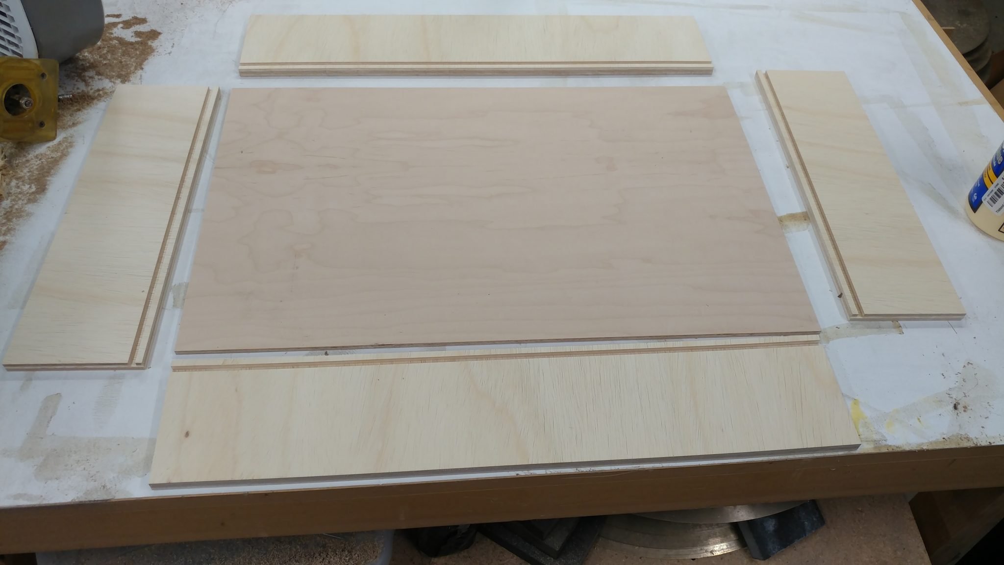
I dry fit the workpieces to make sure everything fits together well. The bottom and the two inner walls don’t have any dadoes, grooves, or rabbets.
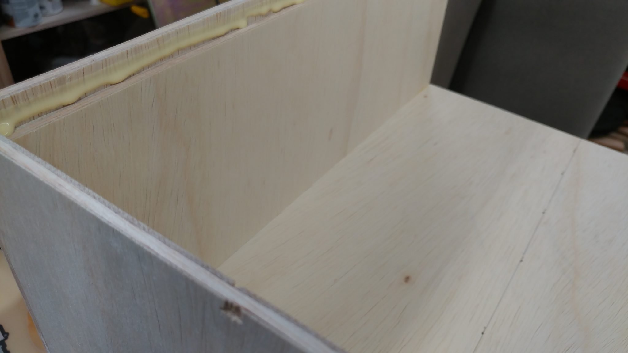
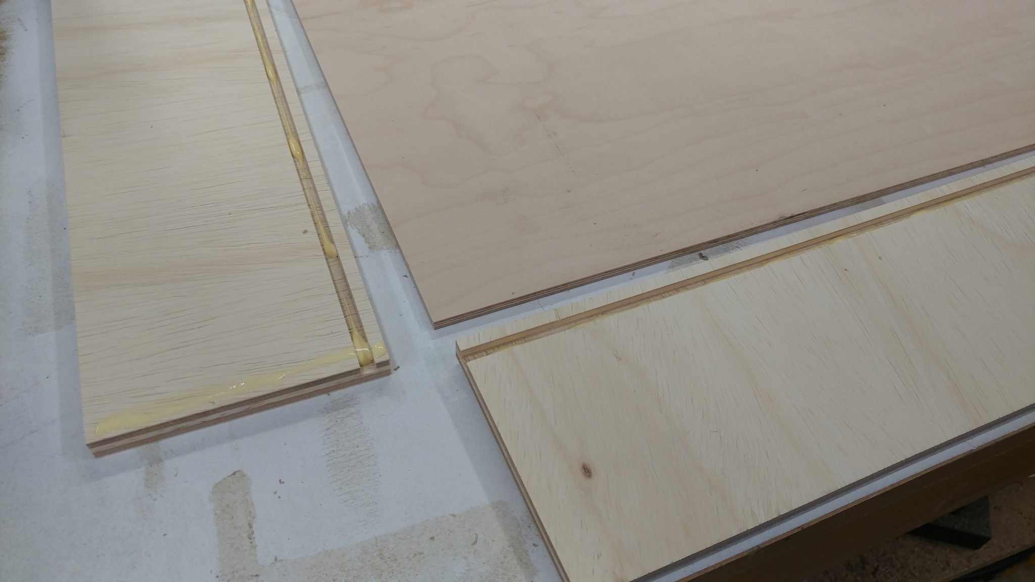
For the glue-up I started by putting a bead of Titebond 2 in all of the dadoes.
I placed the horizontal workpiece in its corresponding dado on the back piece. Then I inserted the vertical pieces in their corresponding dadoes on the horizontal piece and the back piece.
I used a combination square to mark a line on the underside of the horizontal workpiece directly underneath the dadoes.
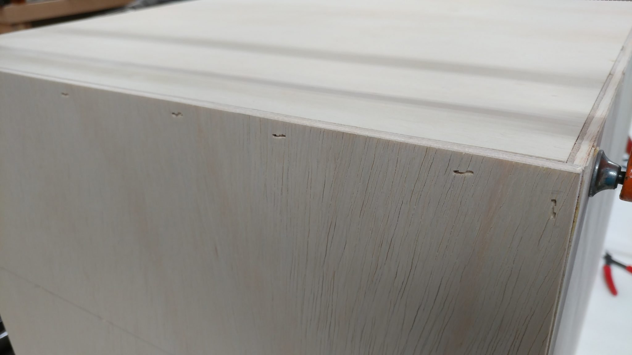
I secured the pieces down by adding nails with a nail gun along the lines I drew.
I then did the same thing on the back.
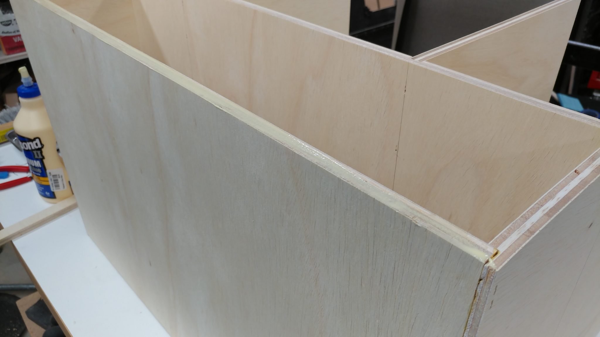
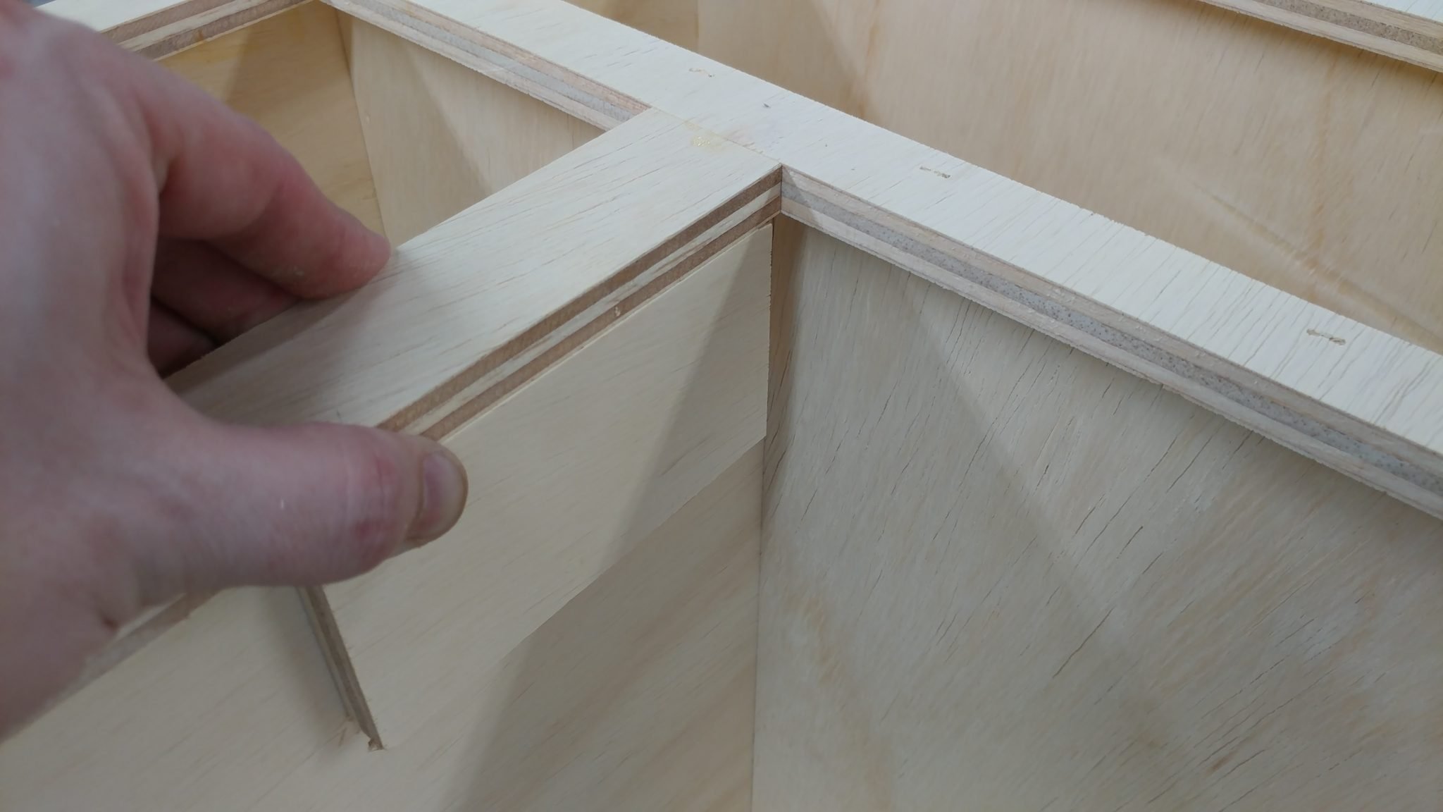
I attached both side pieces by adding a bead of glue in the dado and along the rabbet on the back edge.
The side pieces slid right into position and I made a line to correspond with the horizontal piece.
I nailed the side on along the back edge and the line I just drew.
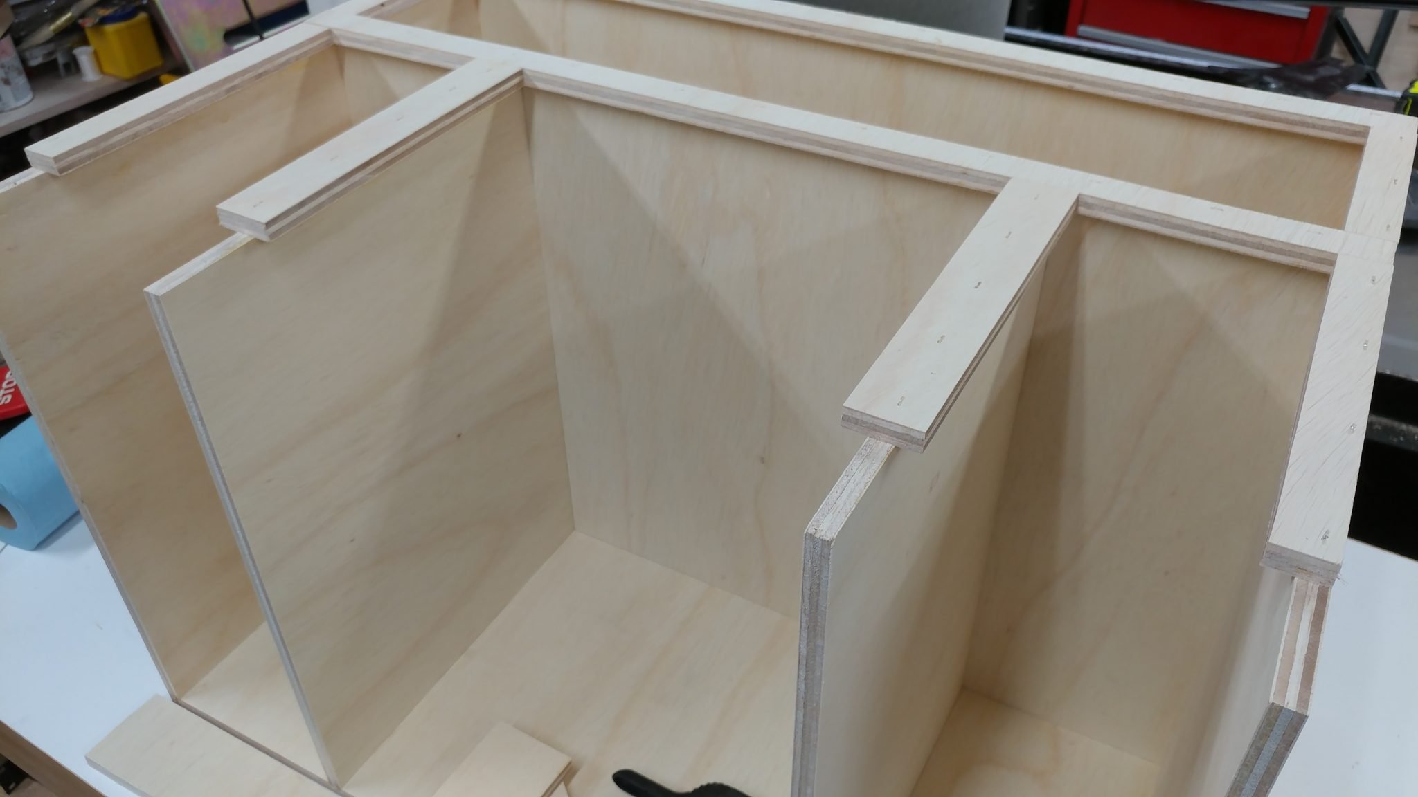
To attach the bottom, I flipped the assembly upside-down.
I ran a bead of glue along the rabbets that I put on the bottom edges.
Then I nailed it in place.
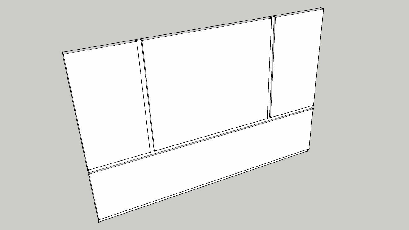
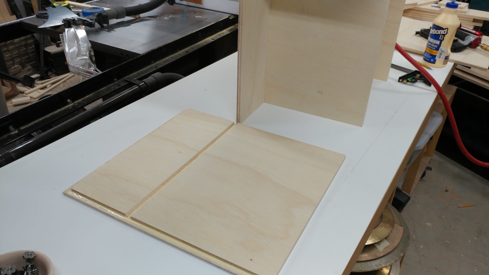
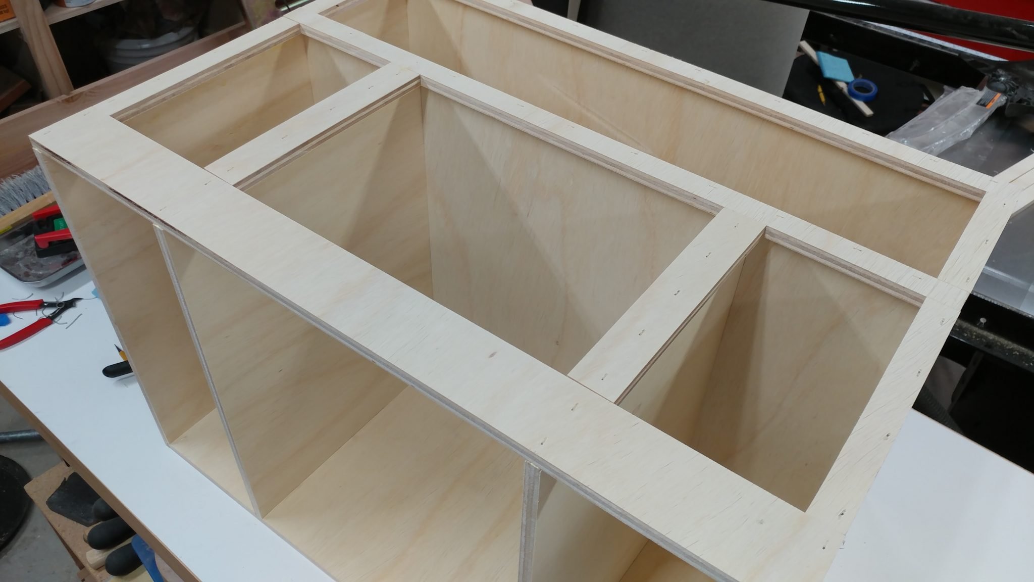
I decided to piece together the front rather than cut it out of a single sheet because I didn’t want to waste any plywood if I could avoid it.
I laid the enclosure on it’s back so the front was facing upward. I then started attaching the pieces of the front starting from the bottom.
Since this is being put together from several smaller pieces, they don’t always align perfectly. This is fine. I’ll deal with this before I attach the laminate.
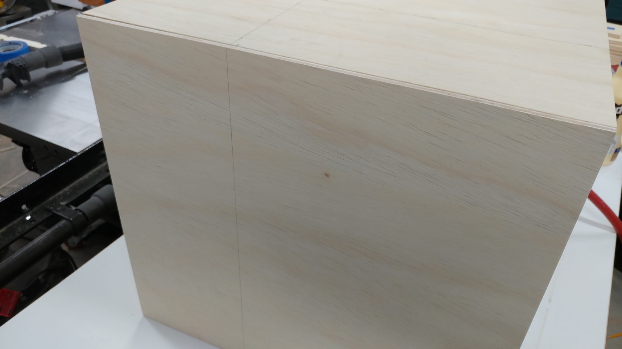
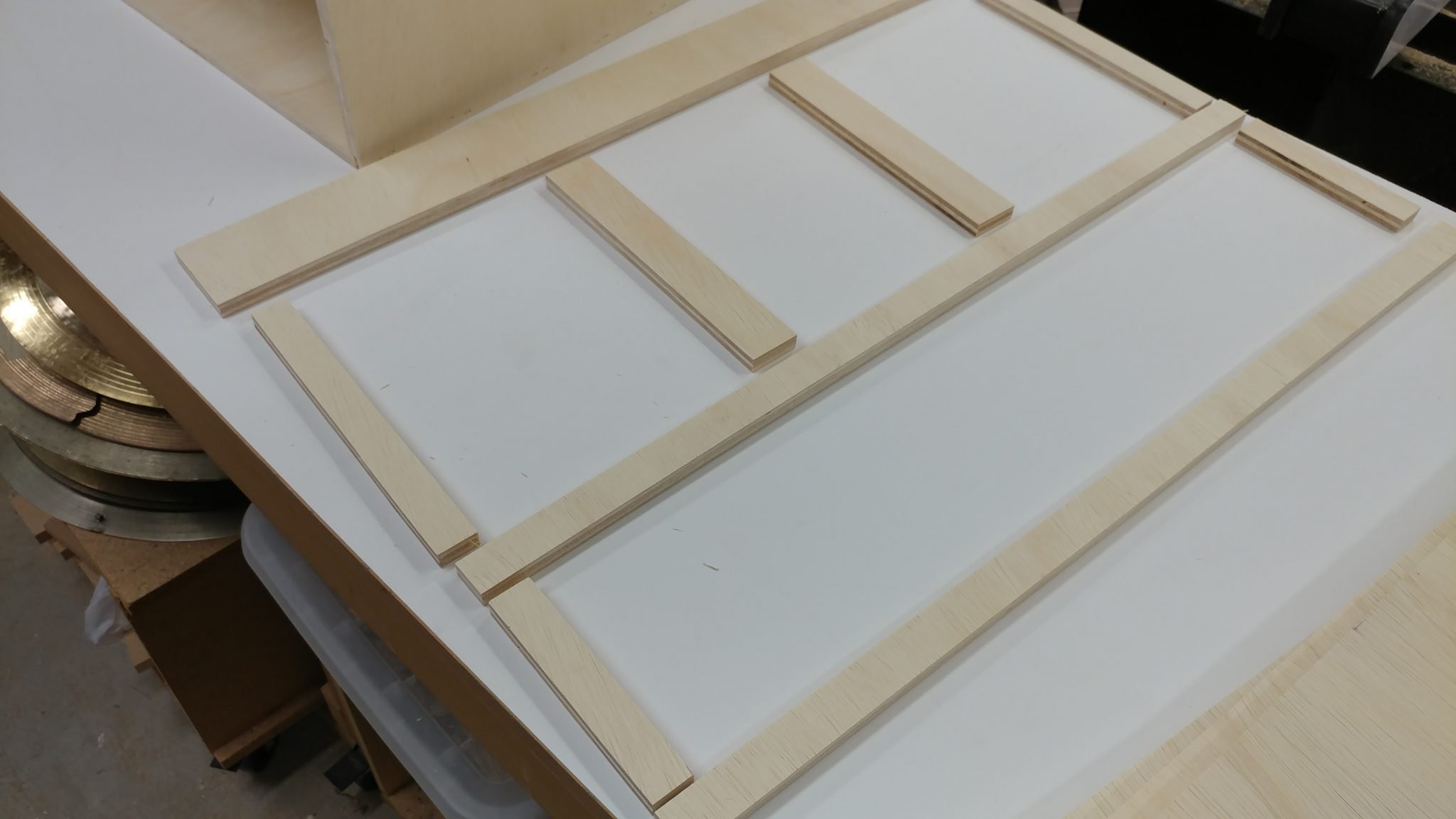
I then attached the vertical pieces. The outer ones went on easily. The inner walls are 1-1/2″ wide so they should overhang the vertical wall with 1/2″ on each side. I used two scrap pieces of the 1/2″ plywood to help position the vertical pieces, starting from the lower end and nailing it down before moving up to the top.
I eyeballed the placement of the nails and managed to not screw this part up. All that’s left is to attach the top horizontal piece. I purposely cut this piece a bit wider than I needed, just in case the front pieces didn’t assemble as cleanly as I wanted. I placed the piece in place and marked where I needed to trim it down.
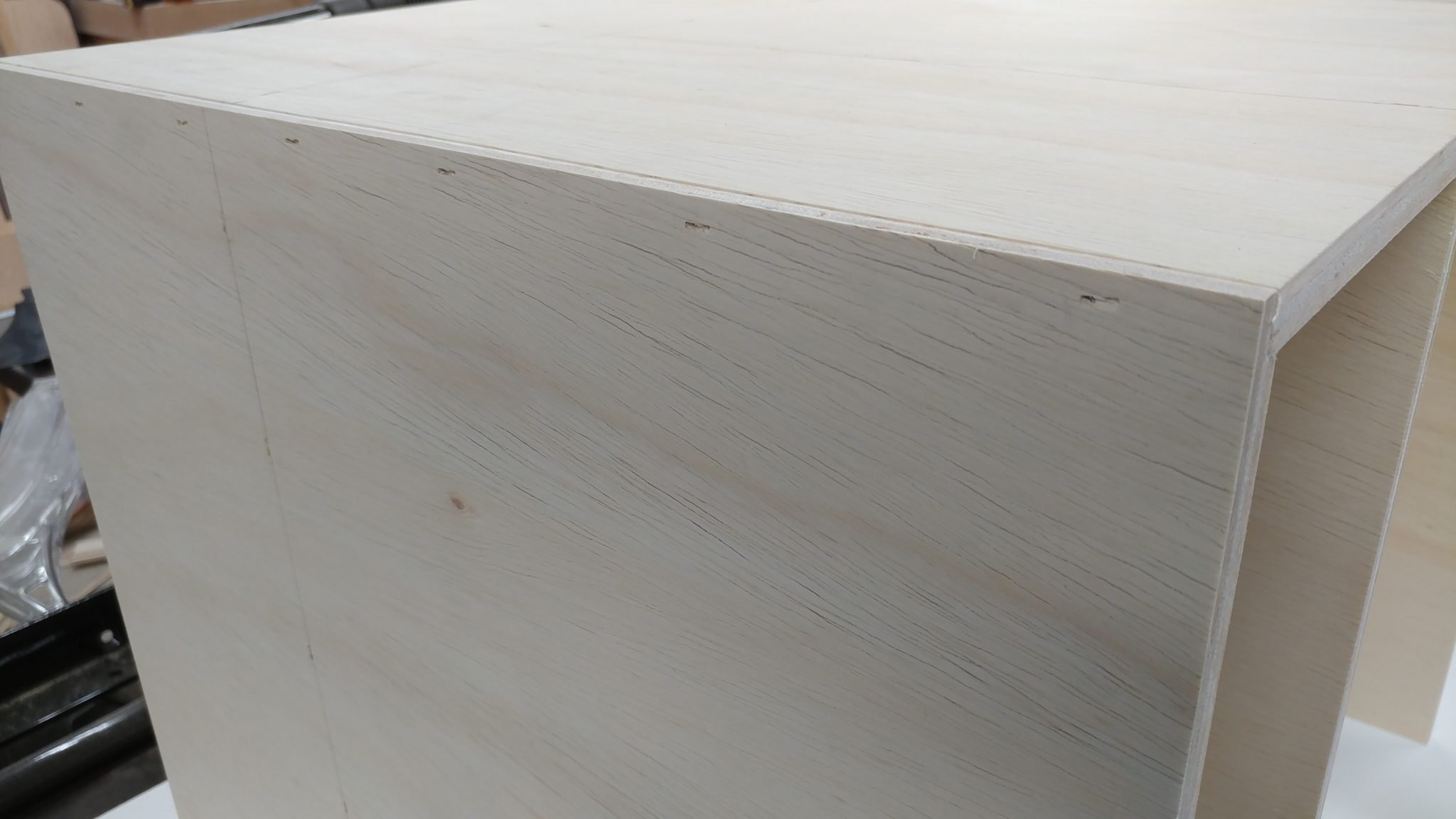
I then applied some glue on the remainder of the vertical walls and finished it up by nailing it in place.
This is where I realized that I trimmed the top front piece a bit too much so it sits about 1/32″ too low. That’s well within my own tolerance range for this project so I’m going to let it slide.
Making the drawers.
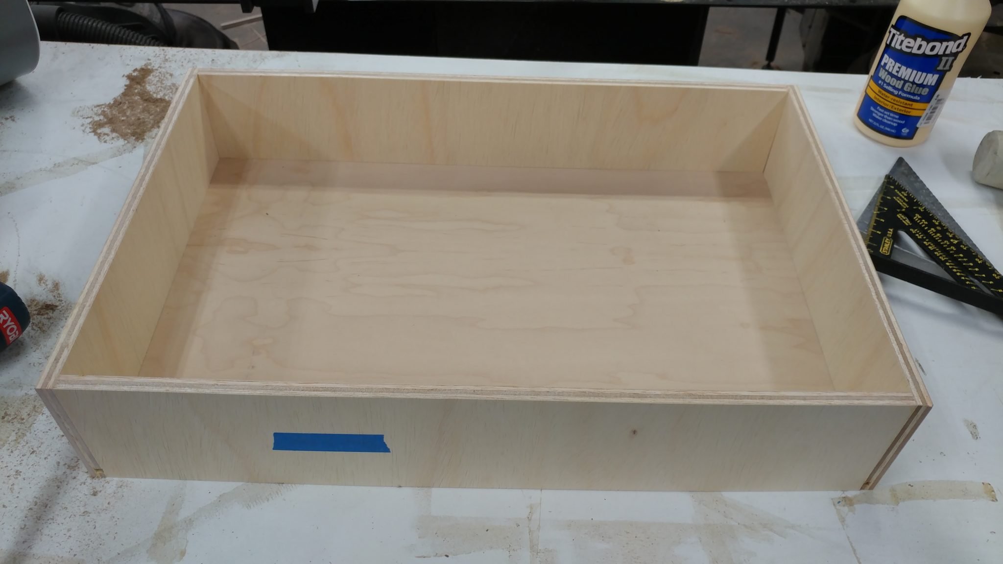
I didn’t do anything fancy for the main drawer. It’s very utilitarian. I just cut out the sides and put a 1/4″ dado (or groove) in each piece for the drawer bottom. With the pieces cut, I laid them out for easier assembly.
I applied some Titebond 2 wood glue to the dado and along the side pieces where they will meet up with the front and back.
I then assembled it and secured it with some nails.
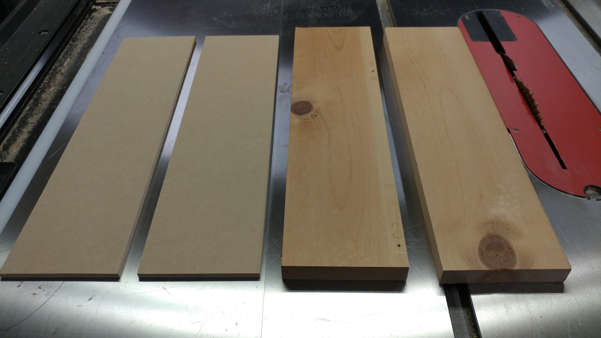
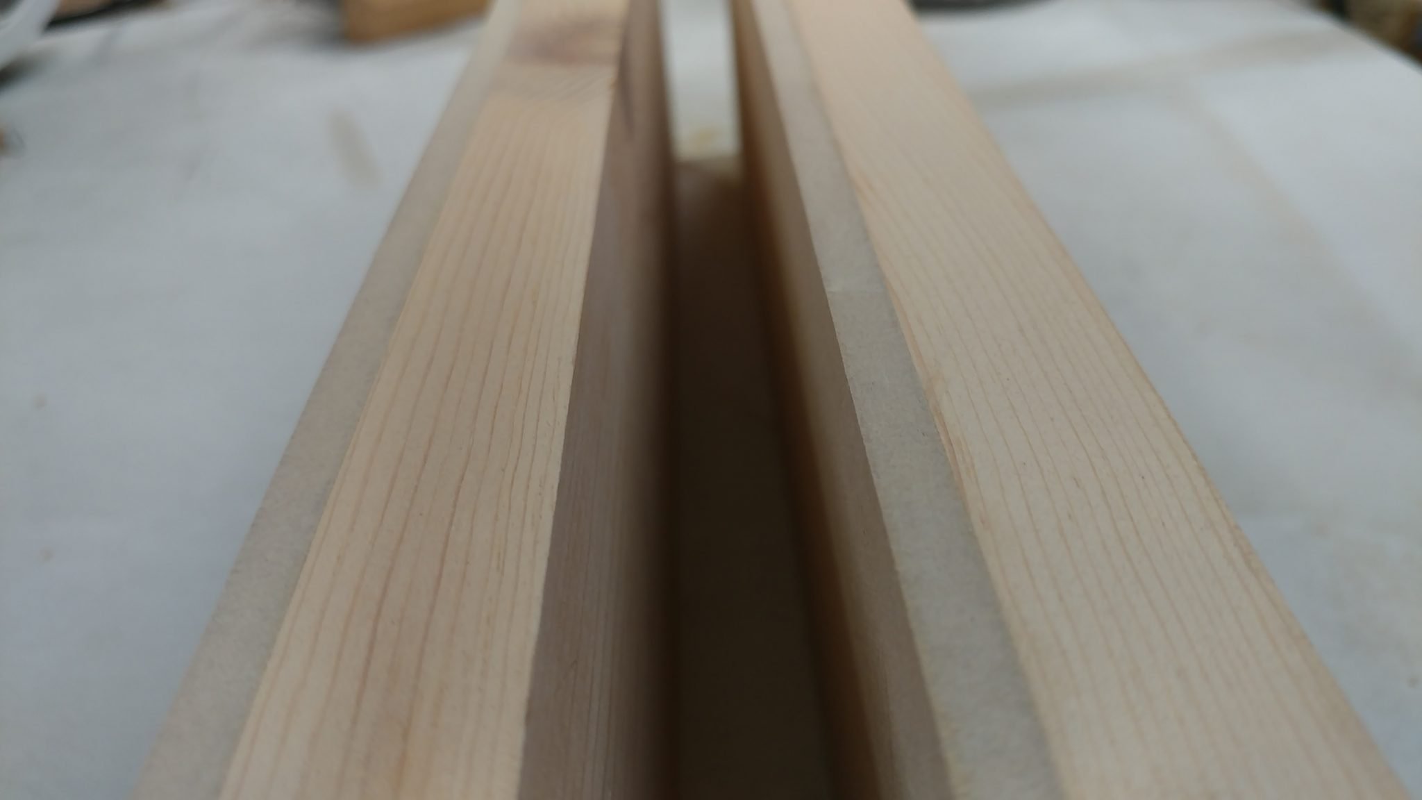
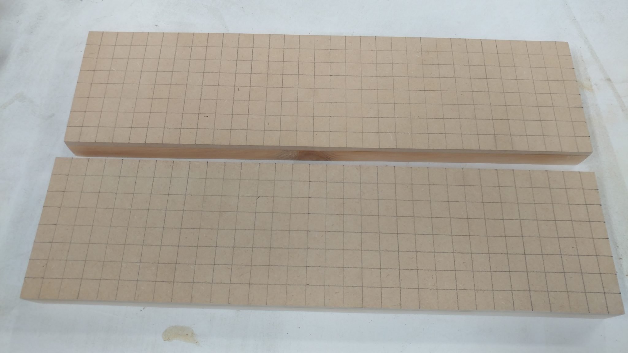
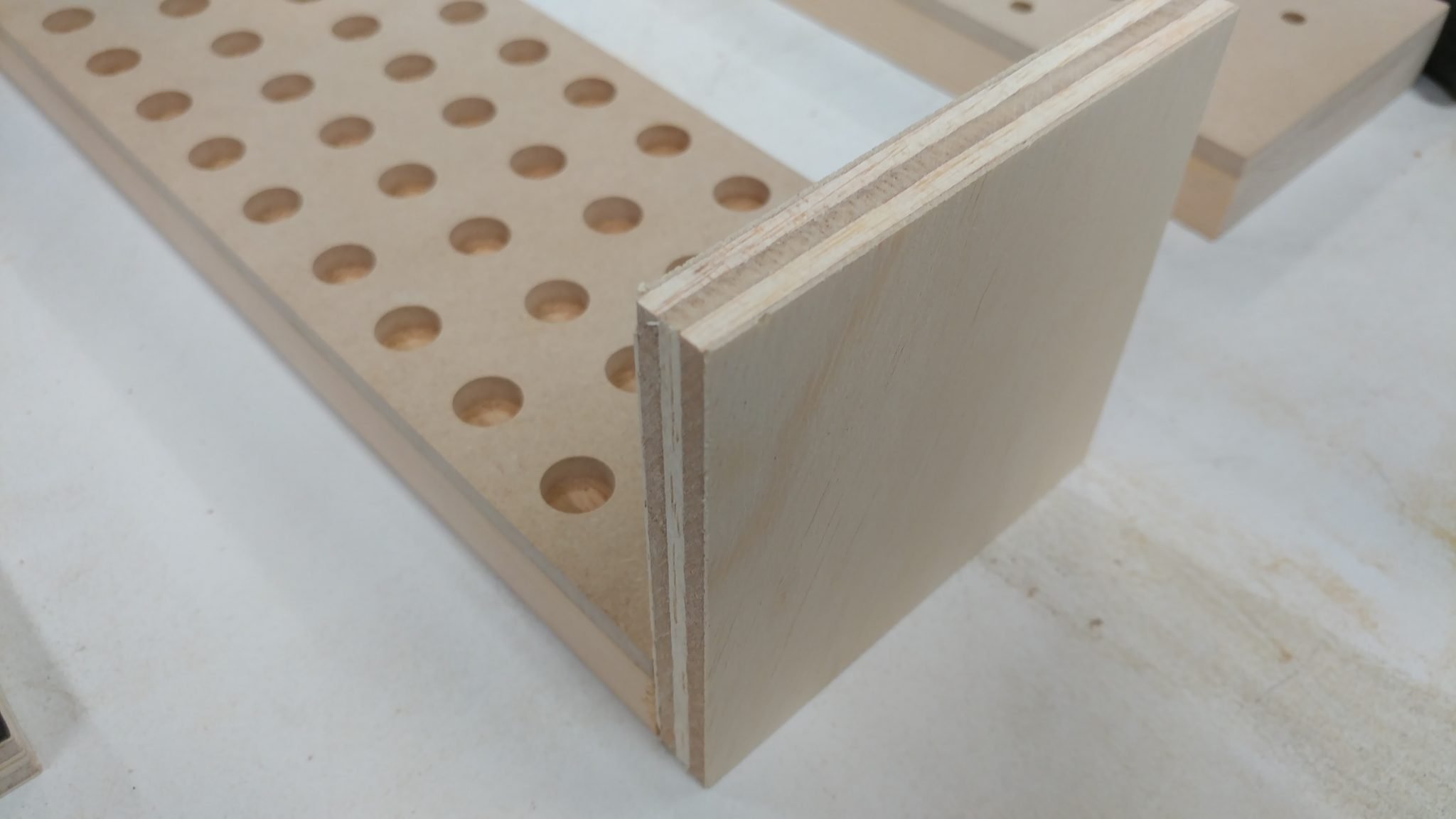
The router bit storage drawers are a bit different. I decided to just make drawers without sides. I also wanted the bottom of them to be 1″ thick so I cut down some pine to make the bottom boards then some matching 1/4″ MDF for the top surface.
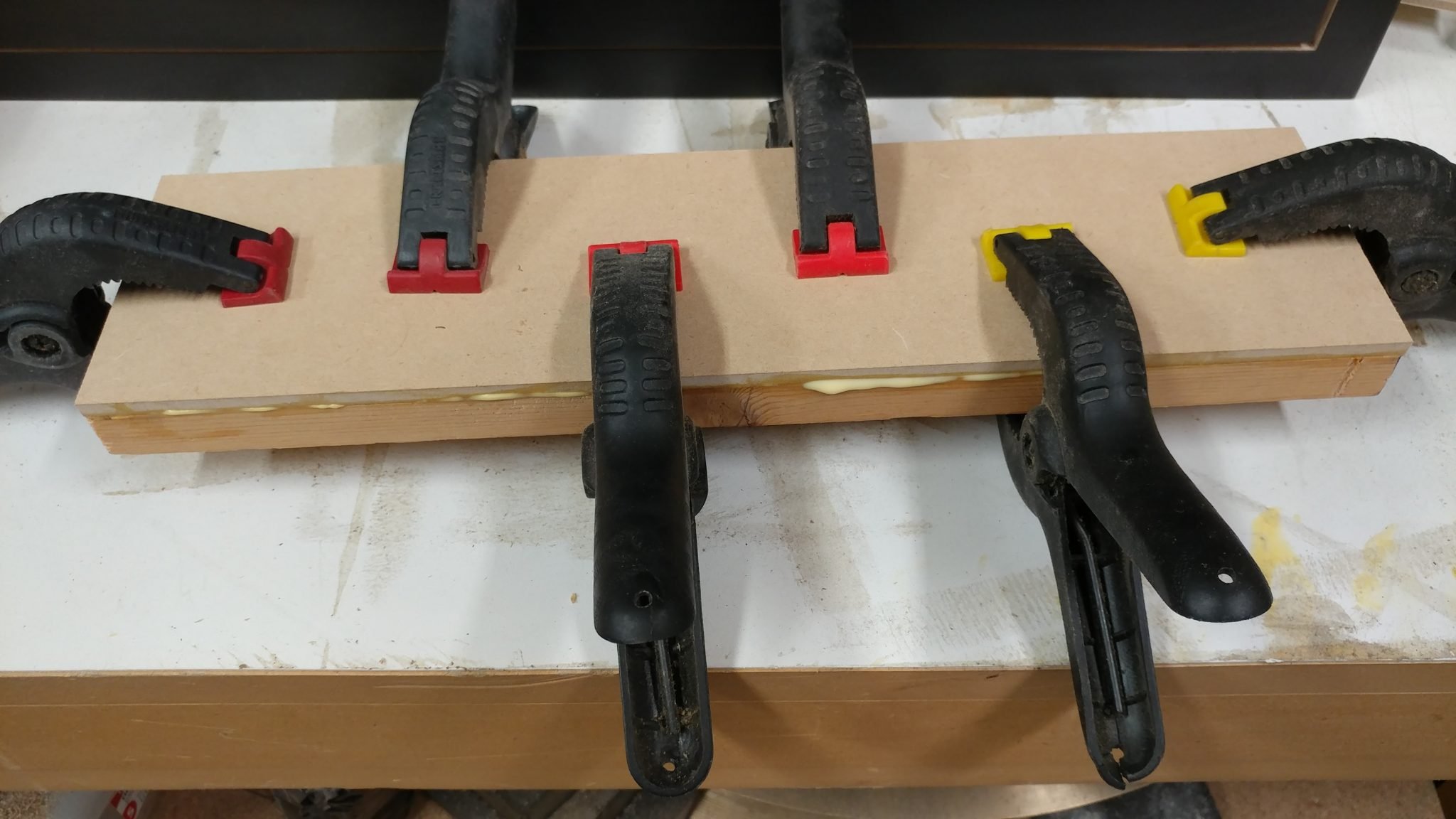
I glued them together and clamped them up.
After drying overnight, there was quite a bot of glue squeeze-out that needed to be sanded away. I used a random orbital sander to sand it smooth.
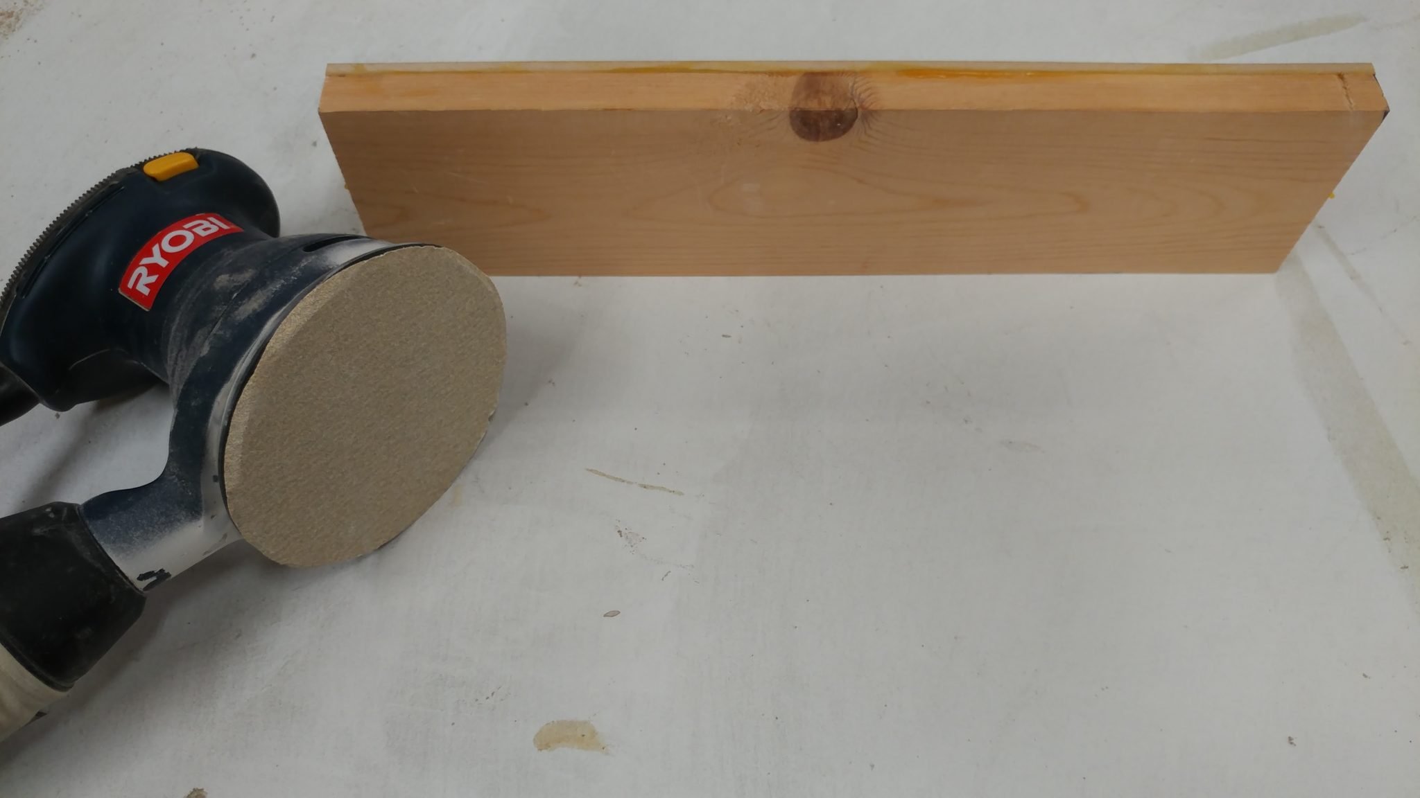
After a bit of sanding, I got it all smooth.
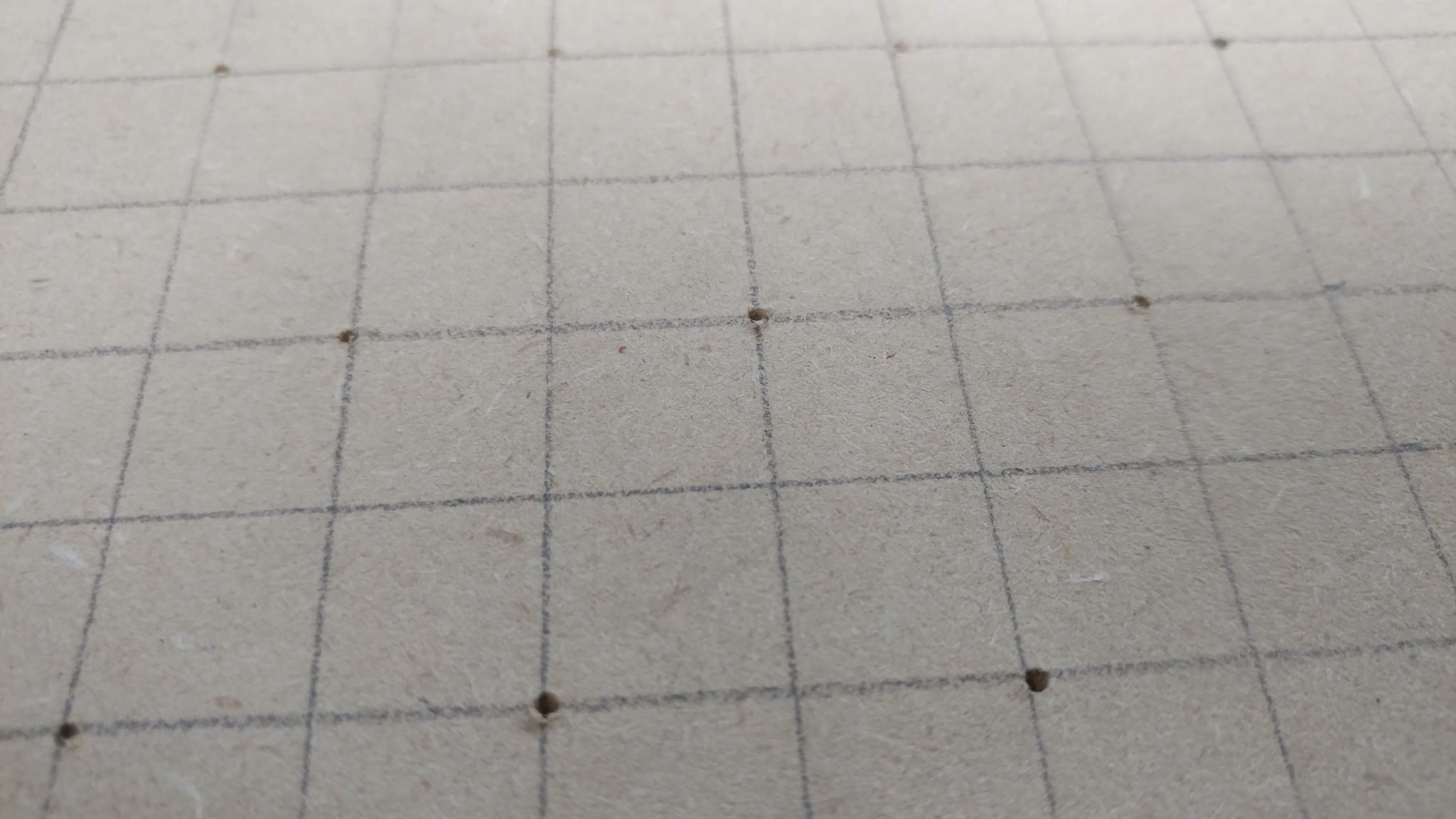
I drew a 1/2″ grid on top of the MDF to help lay out the hole pattern.
I used an awl to punch a hole pattern. I decided to space them 1″ apart down the length of the drawer and each row staggered 1/2″.
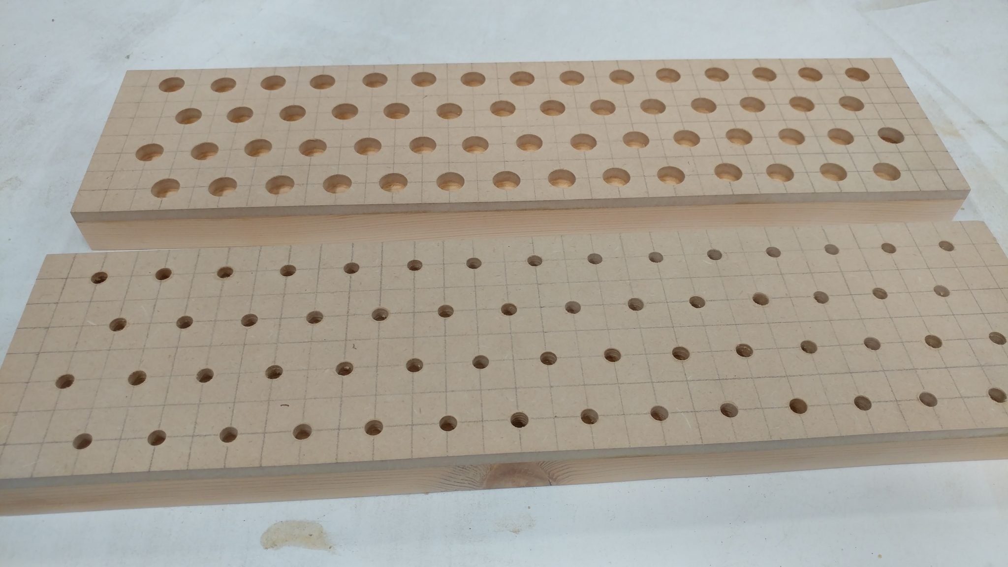
I set my drill press to drill halfway through the material. After a lot of tedious drilling with both 1/4″ and 1/2″ forstner bits, I finally got all the holes drilled.
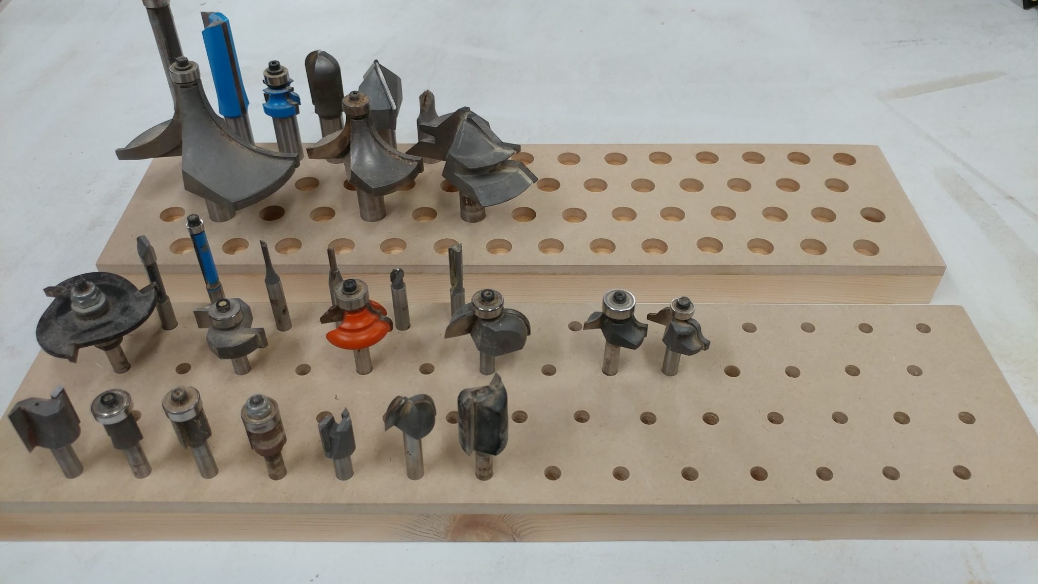
I sanded the top smooth which got rid of the pencil marks and did a test fit with some of my router bits.
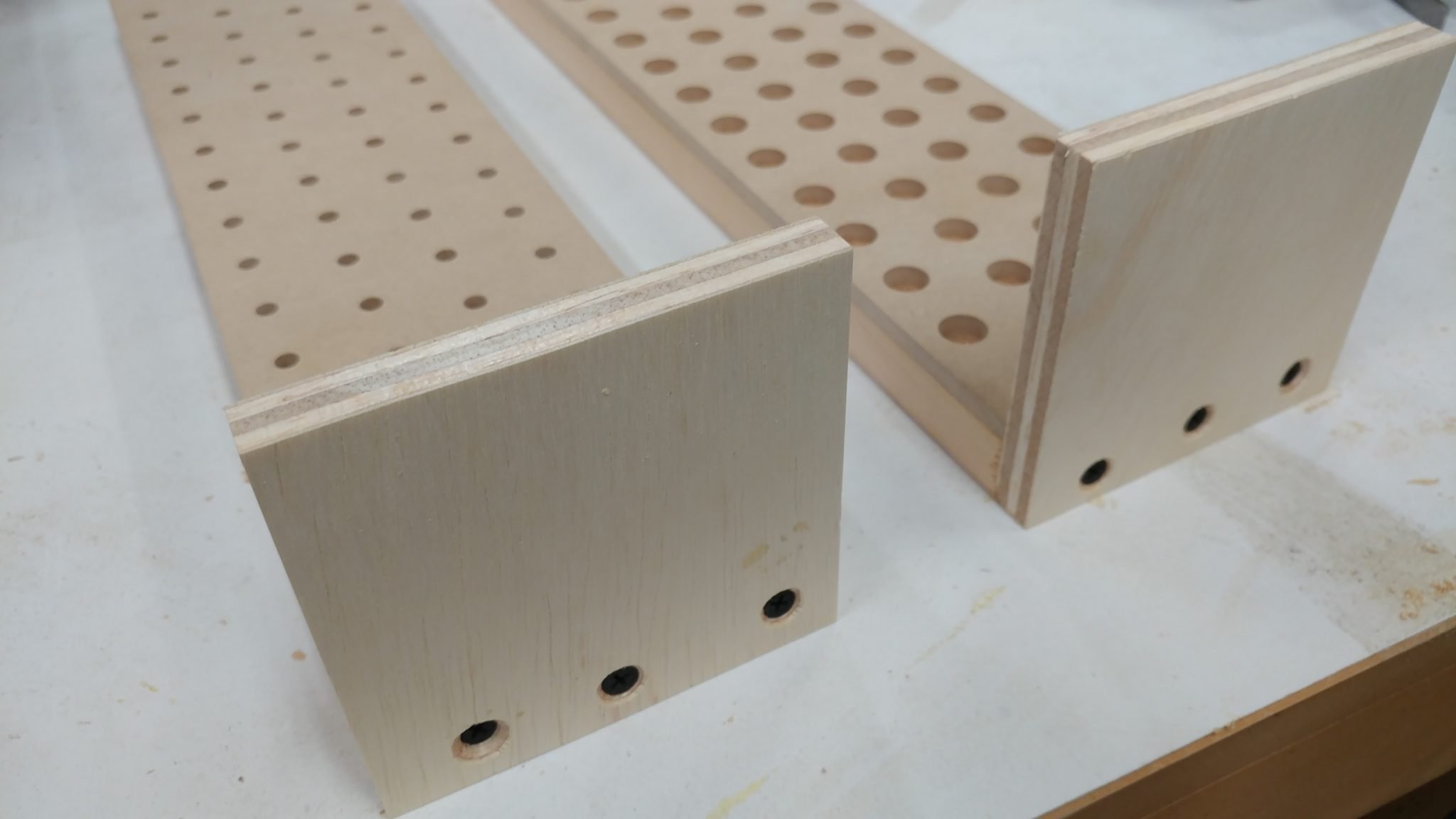
The drawers will have a front piece that the drawer face will attach to. This is a simple piece of 3/4″ plywood cut to the width of the drawer and 1/2″ shorter than the height of the drawer face.
I pre-drilled and countersunk the holes for some drywall screws to attach the front to the base. Then I glued and screwed them together.
That’s it for the main cabinet carcase. In the next article, I’ll cover applying the laminate. I’ll follow that up with adding the hardware, doing the electrical, and attaching it to the underside of the table.
If you have any questions or suggestions, please leave a comment below.
>> Continue on to Table Saw Modification – Router Table Enclosure: Part 2 – Laminate
Pingback: Table Saw Modification - Router Table Enclosure: Part 2 - Laminate - TrentDavis.net
Pingback: Table Saw Modification - Router Table Enclosure: Part 3 - Hardware and Electrical - TrentDavis.net